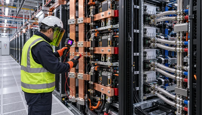
The Thermodynamic & Physical Wall of 48V DC in 120kW+ Hyperscale Compute Racks
Hyperscale AI infrastructure is experiencing an unprecedented surge in volumetric power density, driven by clusters of high-TDP accelerators and graphics processing units (GPUs) consuming between 700W and 1,500W per package. As aggregate server rack power requirements escalate from historical baselines of 40kW to between 120kW and 140kW, the conventional 48V direct current distribution architecture standardized by Open Rack v3 reaches an insurmountable thermodynamic and electromagnetic threshold. Delivering 120kW at a nominal 48V DC rail requires sustained steady-state currents in excess of 2,500A. Under these current levels, I²R resistive losses within power distribution planes, backplane busbars, and power blind-mate connectors generate prohibitive thermal penalties directly in the inlet airflow path of compute trays, exacerbating chiller infrastructure loads.
To mitigate conduction losses at 2,500A, busbars must feature cross-sectional copper areas exceeding 800 mm², translating to continuous copper distribution masses greater than 15 kg per vertical rack meter. This mechanical mass severely obstructs chassis ventilation channels, restricts high-density liquid-cooling manifold routing, and imposes excessive structural load on datacenter flooring frames. Furthermore, localized milliohm contact resistances across modular shelf blind-mate connectors trigger localized thermal runaway and unsustainable voltage drops across the vertical distribution path. Transitioning to a bipolar ±400V DC architecture (providing 800V line-to-line across outer conductors and ±400V with respect to a centered neutral conductor) slashes the required rack supply current to roughly 150A for an equivalent 120kW load. This current reduction of more than 80% yields a quadratic reduction in I²R transmission dissipation, freeing internal chassis volume for direct-to-chip cooling loops and advanced optical transceivers.
Audit existing 48V/54V copper busbar voltage drops and thermal dissipation across all racks exceeding 80kW nominal load.
Calculate copper mass reductions and aerodynamic volumetric clearance gains achieved by scaling busbar voltages to ±400V DC.
Analyze rack-level I²R resistive losses to identify parasitic thermal loads that artificially degrade cooling efficiency and Power Usage Effectiveness (PUE).
DC Short-Circuit Dynamics & The Arc Extinction Failure of Mechanical Breakers
Direct current fault interruption presents severe physical challenges that do not exist in conventional alternating current systems. In AC infrastructure, the sinusoidal waveform naturally forces current through zero-voltage crossings every 8.33 or 10 milliseconds (at 60Hz and 50Hz, respectively), enabling mechanical contacts within molded case circuit breakers (MCCBs) or air circuit breakers to quench the electric arc via de-ionizing arc chutes. Conversely, high-voltage DC lacks a natural zero-crossing point. When a low-impedance short circuit occurs on a ±400V DC power distribution bus supported by low-equivalent-series-resistance (ESR) electrolytic or metalized film DC-link capacitor banks, stored energy discharges into the fault location almost instantaneously.
Under these circumstances, prospective short-circuit fault currents routinely exceed 50 kA within tens of microseconds, with the rate of current rise (di/dt) frequently surpassing 150 A/µs, governed strictly by parasitic busbar loop inductance and capacitor ESR. Traditional electromechanical circuit breakers require 5 to 15 milliseconds merely to separate physical contacts and initiate mechanical arc elongation. During this multi-millisecond window, the DC rail voltage collapses across the entire rack row or power domain. This instantaneous voltage sag drops below the hold-up limits of downstream Intermediate Bus Converters (IBC), inducing unrecoverable power outages across operational AI training nodes. Simultaneously, unquenched DC arcs generate catastrophic plasma explosions, destructive arc flash energies, and molten copper vaporization that permanently damages adjacent power shelves.
Simulate prospective DC fault discharge curves using precise capacitor ESR, busbar parasitic inductance (L_bus), and low-impedance bolting assumptions.
Determine maximum hold-up time windows across rack power supply modules to establish worst-case bus collapse tolerance thresholds.
Assess incident arc energy exposures under NFPA 70E for high-voltage DC distribution to confirm mechanical protection inadequacies.
Solid-State Circuit Breakers (SSCB): Wide-Bandgap SiC/GaN Nanosecond Protection
Mitigating sub-microsecond DC fault surges demands an absolute departure from mechanical contactors toward fully static Solid-State Circuit Breakers (SSCB) leveraging wide-bandgap (WBG) semiconductors. Built using discrete power Silicon Carbide (SiC) MOSFETs or monolithic bidirectional Gallium Nitride (GaN) devices configured in anti-series or common-source topologies, modern SSCBs eliminate mechanical inertia completely. SiC power devices offer exceptional critical electric breakdown fields (>3 MV/cm) and high thermal conductivities, allowing low specific on-state resistances (R_ds(on)) that minimize steady-state conduction losses during continuous 150A to 300A rack power delivery. When married to ultra-fast desaturation detection circuitry or differential Rogowski coils monitoring line di/dt, the SSCB identifies anomalous fault conditions within 150 to 200 nanoseconds.
Upon fault validation, the SSCB gate drive sub-tier actively pulls the SiC gate negative, fully quenching the forward current path within 1.5 to 2 microseconds. However, arresting thousands of amperes moving through distribution busbar inductances in microsecond timeframes induces extreme inductive flyback voltage spikes according to Faraday's law of induction (V_spike = L_bus * di/dt). Left unmanaged, these transient overvoltages easily pierce the dielectric oxide and reverse-blocking capability of 1200V-rated SiC dies. Advanced SSCB architectures counter this by tightly co-packaging high-energy metal-oxide varistors (MOVs) and fast-clamping transient voltage suppression (TVS) diodes directly across the semiconductor switches, reinforced by custom RC or RCD snubber networks. This coordinated suppression network shunts reactive inductive energy away from the switching devices, clamping transient peaks safely below semiconductor avalanche limits.
Specify wide-bandgap SiC MOSFET modules exhibiting combined conduction resistances under 10 milliohms per SSCB assembly.
Validate sub-200ns desaturation detection response times across gate driver stages under hard-switching fault-under-load (FUL) scenarios.
Dimension parallel metal-oxide varistor (MOV) energy absorption ratings to handle the maximum lumped inductive energy (0.5 * L * I_peak²) of the rack busway.
Bipolar ±400V Topology, High-Resistance Midpoint Grounding & Voltage Stress Control
The implementation of a bipolar ±400V DC distribution architecture represents an optimal compromise between high volumetric power throughput, insulation safety, and dielectric component stress. The topology establishes three continuous distribution lines throughout the server cluster: a +400V positive pole, a 0V center neutral return conductor, and a -400V negative pole, yielding an aggregate 800V line-to-line potential. Individual rack-level power shelves and intermediate converters are strategically partitioned across the poles—connecting either between +400V and 0V or between -400V and 0V—to dynamically balance the systemic load across the neutral bus. For ultra-dense compute trays, intermediate power converters can span across the full 800V line-to-line differential, halving conversion current demands and optimizing magnetic component volumes.
Crucially, the center neutral conductor is tied to earth reference via High-Resistance Grounding (HRG). This neutral-ground bonding architecture limits line-to-ground human touch potential strictly to 400V DC, conforming to standard low-voltage installation directives while effectively halving the dielectric breakdown stress experienced by primary insulation barriers, chassis clearances, and high-frequency transformer windings compared to unipolar 800V installations. In the event of a single line-to-ground insulation breakdown, the HRG resistor limits fault current to minimal levels, preventing localized weld-faults and allowing the cluster to continue operating safely while diagnostic systems pinpoint the impedance anomaly. Coordinated Zone-Selective Interlocking (ZSI) enabled via deterministic optical interconnects between SSCB nodes ensures only the compromised compute node or power shelf isolates itself, leaving upstream distribution switchboards undisturbed.
Implement High-Resistance Grounding (HRG) at the central neutral point sized to restrict continuous ground-fault currents to less than 5A.
Incorporate automatic phase-balancing algorithms within dynamic rack power shelves to equalize loading across the +400V and -400V rails.
Deploy deterministic optical transceivers for inter-SSCB signaling to achieve microsecond Zone-Selective Interlocking (ZSI) across multi-rack clusters.
End-to-End DC Conversion Hierarchy: Megawatt Central Rectifiers to LLC Point-of-Load
Replacing multistage AC-DC conversions with a streamlined, end-to-end direct current conversion hierarchy unlocks unprecedented systemic efficiency across AI datacenters. Drawing upon decades of mission-critical telecom central office DC architectures, power enters the hyperscale facility through centralized megawatt-scale AC-DC rectifier banks. These utility-scale converters step medium-voltage 480V or 400V three-phase grid power directly into a regulated bipolar ±400V DC distribution backbone, achieving conversion efficiencies equal to or exceeding 97.8% utilizing active power factor correction (PFC) and multi-level Vienna or interleaved bridge topologies. By eliminating redundant internal server power supply units (PSUs) and their accompanying thermal footprints, data center whitespace is freed exclusively for revenue-generating compute infrastructure.
At the server chassis tier, the incoming ±400V (or 800V pole-to-pole) is down-converted through ultra-dense Intermediate Bus Converters (IBC) utilizing resonant LLC zero-voltage switching (ZVS) topologies. These resonant LLC converters operate at switching frequencies exceeding 500 kHz, yielding exceptional power densities while stepping voltage directly down to a 48V or 12V intermediary rail. From this intermediary tier, high-bandwidth multiphase point-of-load (PoL) buck regulators and vertical power delivery (VPD) modules route sub-1V core power directly into GPU dies. To bridge utility grid anomalies and generator ramp times, distributed lithium-ion Battery Backup Units (BBU) and high-power supercapacitor banks interface directly onto the ±400V DC bus via bidirectional buck-boost converters, eliminating double-conversion AC inverter stages and maintaining seamless power continuity.
The overall systemic architecture designed by RICEWIND engineers demonstrates that unifying DC-native compute loads, distributed battery reserves, and centralized megawatt rectification cuts conversion losses by up to 12% across the entire facility. The integration of high-density DC distribution significantly flattens thermal dissipation profiles inside rack envelopes, directly driving down computational cooling overhead.
Deploy centralized megawatt rectifiers with active harmonic cancellation achieving a minimum of 97.8% conversion efficiency at 50% to 100% rated load.
Specify resonant LLC topology for the ±400V to 48V Intermediate Bus Converters (IBC) to maximize zero-voltage switching (ZVS) operational envelopes.
Direct-couple lithium-ion BBU shelves and high-rate supercapacitor modules to the bipolar DC bus using high-efficiency bidirectional DC-DC controllers.
Standardization, Compliance & Deployment: IEEE P2030.10, UL 489I and Field Metrics
The commercialization of bipolar ±400V DC power architectures in high-density AI clusters is reinforced by a rapidly maturing landscape of international safety certifications and technical standards. Key among these frameworks is the IEEE P2030.10 standard for DC microgrids in data centers, which formalizes earthing strategies, voltage quality envelopes, and transient withstand criteria for direct current distribution. Concurrently, regulatory bodies have resolved historical testing gaps surrounding semiconductor-based isolation through draft and newly ratified guidelines such as UL 489I (covering Solid-State Circuit Breakers for overcurrent protection) and UL 943C (regulating ground fault protection). These standards define rigorous requirements for galvanic isolation air gaps, dielectric breakdown withstand, and cyclic thermal endurance under continuous maximum current.
Empirical performance data from early enterprise deployments and hyperscale pilot clusters running 120kW+ AI footprints provide clear validation of the bipolar architecture. In verified commissioning environments, migrating from legacy 48V distribution to bipolar ±400V DC combined with microsecond-class SiC SSCBs yielded an immediate 68% reduction in overall electrical distribution thermal losses. Cabling cross-sectional volume and associated copper weight plummeted by 80%, substantially reducing embodied carbon, structural racking expenses, and mechanical assembly hours. Most significantly, real-world short-circuit fault testing verified zero busbar voltage collapse across adjacent compute trays during localized faults: the SSCB successfully clamped and cleared 45 kA prospective fault currents in 1.8 microseconds, keeping adjacent cluster nodes entirely uninterrupted.
Ensure all solid-state circuit breaker hardware complies with UL 489I testing criteria for dielectric isolation and semiconductor endurance.
Align physical infrastructure layout and touch-safety shielding with IEEE P2030.10 and NFPA 70E Class 1 DC boundary regulations.
Track operational telemetry (transient overvoltages, leakage currents, and thermal deltas) to build validation records for insurance and certification compliance.
Engineering Procurement & Technical Desk
For technical datasheets, custom power topology design, or volume export quotations, reach out to HEFENGQI engineers.