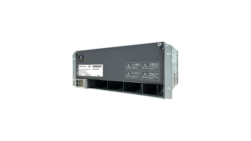
1. Rectifier Parallel Current-Sharing Mechanism and Imbalance Alarm Thresholds
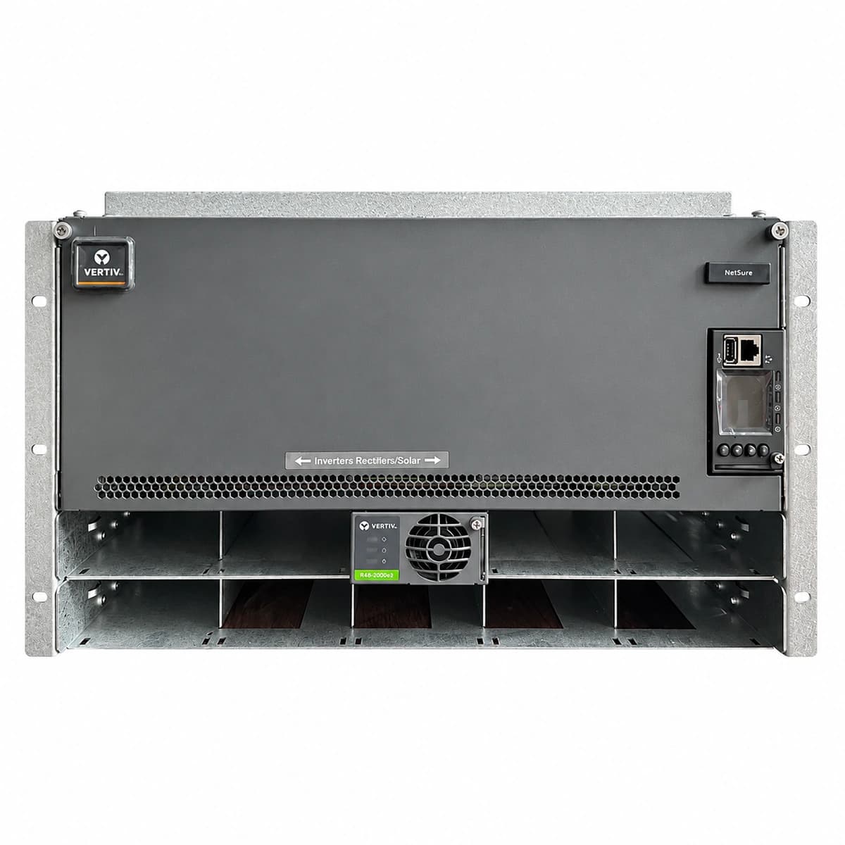
In -48V DC power distribution frameworks across telecom base stations and modular data centers, rectifiers operate in N+1 or N+X redundant parallel architectures. High-efficiency modules (such as Vertiv R48-3500e and Huawei R4850G2) utilize high-speed digital CAN bus signaling or autonomous droop-sharing algorithms to constrain load deviation within +/- 1.5A of the system mean.
Standard Imbalance Warning Criteria (Industry Norms):
Yellow Indicator (Moderate Imbalance): Triggered when average system current exceeds 20% of rated capacity and a module's deviation from the group mean surpasses 16% (e.g., >8A-11.7A on a 50A rated unit), raising an alarm to the central supervisory unit (CSU).
Red Indicator (Critical Imbalance / Stall): Engaged when system average current is >= 20% while individual module output decays below 2% of rating, indicating complete idle stall, back-feeding risk, or locked PWM output.
DC Bus Circulating Current Risk: An open-circuit voltage variance exceeding 150mV between modules forces the higher-potential unit to back-feed neighboring rectifiers at light loads, dramatically shortening OR-ing MOSFET lifespans.
2. Three Root Causes of Rectifier Current Imbalance
Field diagnostic data proves that load-sharing anomalies rarely stem from isolated component failures; they typically result from coupled physical bus resistance, digital signaling degradation, and analog sampling drift.
Diagnostic Root Cause Matrix:
CAN Bus Physical Layer Degradation and Missing 120-Ohm Termination: Absence of shielded twisted-pair cabling on CAN_H/CAN_L differential paths or uninstalled 120-ohm bus end resistors (system static bus resistance must measure ~60 ohms). Dropped data frames force rectifiers into unsynchronized standalone mode.
Unequal Contact Impedance to the DC Busbar: Oxidized blind-mate rear connectors, inadequate bolt torque specs (< 3.5 N-m), or asymmetrical copper busbar track lengths generate milliohm-level drops that distort physical voltage equilibrium.
DSP Voltage Reference Drift: Long-term thermal cycling or transient lightning surges induce drift in precision secondary feedback dividers or DSP ADC reference voltages, causing inaccurate local potential measurements.
3. Four-Step Closed-Loop Diagnostic and Calibration Protocol
Engineers must adhere strictly to systematic isolation procedures: isolate communication signals, measure static impedance, and verify dynamic stepped load behavior.
Step 1 (CAN Bus Static Resistance Audit): Disconnect the monitoring controller (CSU/SMU) and measure differential resistance between CAN_H and CAN_L pins on the backplane. The reading must strictly fall within 54-66 ohms. A reading of 120 ohms flags an open-circuit terminator, while ~0 ohms indicates a pin short.
Step 2 (Thermal Imaging of Backplane Bus Contacts): Under a steady 50% system load for 30 minutes, inspect rectifier output blade connectors with an infrared thermal imager. Any temperature differential exceeding 15°C between slots mandates contact de-oxidation and retorquing.
Step 3 (Offline Single-Module Voltage Normalization): Withdraw all modules. Re-insert each unit individually with CAN cables disconnected, and measure open-loop float output using a calibrated 5.5-digit multimeter. Calibrate float voltage to precisely -53.50 VDC (+/- 20mV).
Step 4 (Supervisory Unit Handshake & Load-Step Verification): Re-seat all modules and the monitoring unit. Apply dummy load steps at 30%, 60%, and 90% capacity, verifying that inter-module current variance remains well within +/- 1.5A.
4. Preventive Maintenance and Lifecycle Best Practices
Establish biannual scheduled inspections to verify firmware parity across all installed rectifier slots, preventing algorithmic droop mismatches caused by combining distinct hardware generations in the same rack.
For telecom power plant upgrades, OEM rectifier compatibility replacements, or complex bus-sharing diagnostics, contact the RICEWIND technical engineering team: lee@ricewind.com | +86 17621197907
Engineering Procurement & Technical Desk
For technical datasheets, custom power topology design, or volume export quotations, reach out to HEFENGQI engineers.