The AI Triple Constraint: Power, Predictability, and Time-to-Token
Hyperscale AI infrastructure delivery has encountered an acute structural disconnect: while GPU microarchitectures iterate on 12-to-18-month cycles, traditional stick-built data center construction lifecycles span 36 to 60 months. This timeline is primarily driven by medium-voltage utility interconnection backlogs, local zoning approvals, and chronic skilled electrical/mechanical labor deficits. High-density training clusters, typified by the Nvidia GB300 NVL72 and emerging Vera Rubin platforms, demand sustained localized densities between 120kW and 140kW+ per rack footprint. Conventional facilities engineered for legacy 10kW to 20kW air-cooled enclosures cannot accommodate these thermal and mechanical loads without massive structural retrofits, complex raised-floor structural reinforcements, and custom ducting that fundamentally degrade project delivery timelines.
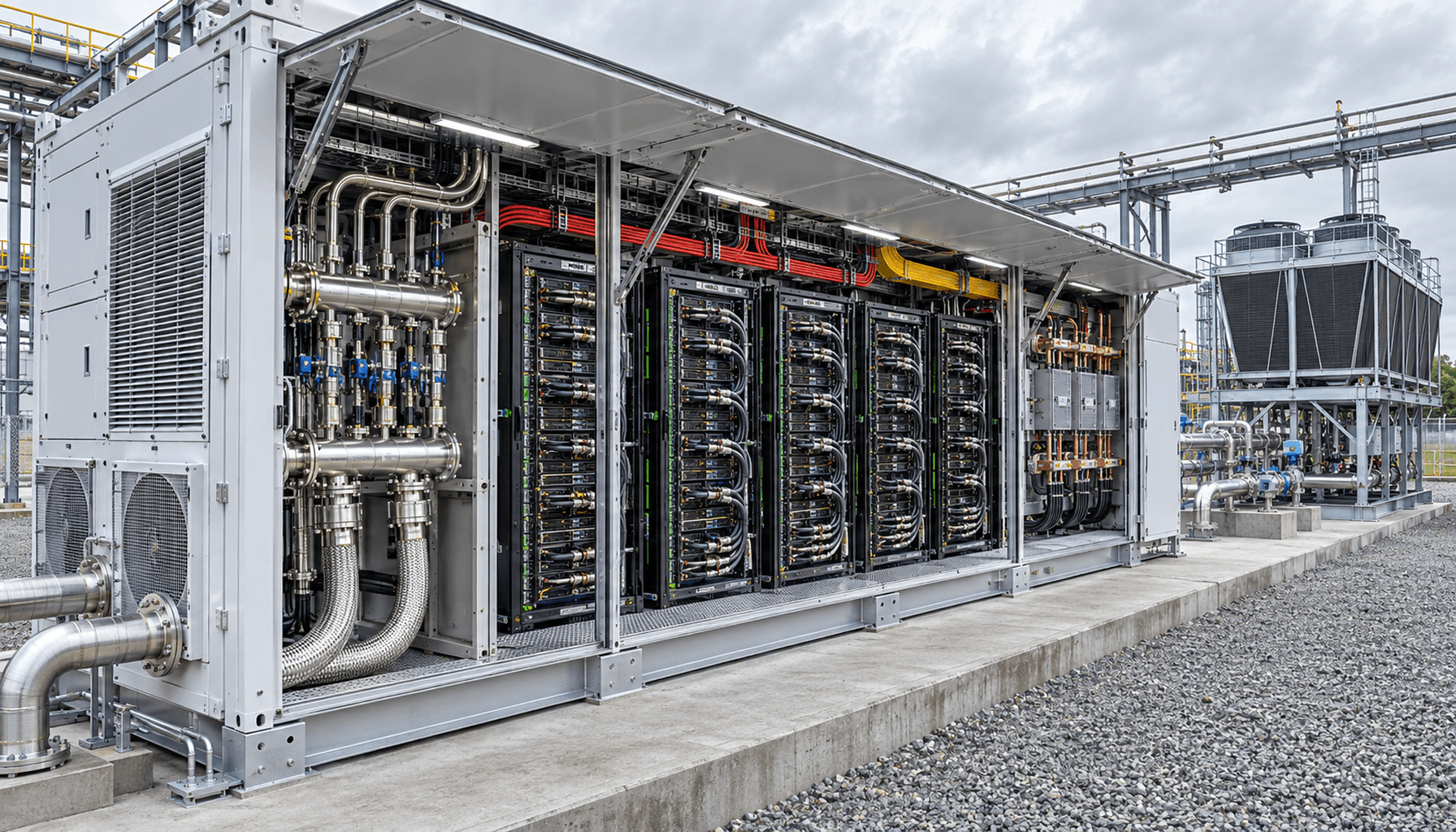
Factory-manufactured modular AI data center architectures resolve this impedance mismatch by transferring up to 90% of structural, thermal, and electrical integration into tightly regulated, cleanroom-adjacent manufacturing lines. Built upon pre-engineered skids or modified ISO structural frames, a 3.5MW modular block arrives on site with switchgear, busways, redundant Coolant Distribution Units (CDUs), and process instrumentation fully integrated and pre-commissioned. This industrial paradigm shifts parallel site civil engineering—such as poured concrete slabs and primary utility stubs—out of the critical path. Consequently, modular deployments compress the commissioning schedule from several years down to weeks, radically reducing time-to-first-token and mitigating the substantial cost of unutilized capital assets.
The economic efficiency of modular scaling is governed by the time value of compute capital. With cutting-edge AI accelerator clusters depreciating rapidly over a 36-month technological half-life, a 12-month construction delay erodes roughly 33% of the cluster's peak revenue potential. By packaging multi-megawatt blocks into repeatable, factory-tested physical envelopes, operators decouple compute deployment from centralized hyperscale campus lead times. This allows instantaneous monetization of regional power allocations, behind-the-meter generation, and stranded energy nodes without waiting for substation expansions.
Verify that site civil design adheres to minimum slab bearing capacity specifications (typically >2,500 kg/m²) to support concentrated 140kW rack masses.
Conduct structural finite element analysis (FEA) on modular skids to guarantee seismic zone 4 compliance during transportation and operational loading.
Ensure utility interconnect specifications support stepped modular energization to avoid localized distribution feeder trips during transformer inrush.
Validate environmental clearances for NEMA 4X / IP66 enclosures under local wind shear and extreme ambient precipitation conditions.
Direct Liquid Cooling (DLC) Fluid Mechanics and Closed-Loop Heat Rejection
At compute packaging densities exceeding 1,000W to 1,500W Thermal Design Power (TDP) per accelerator, air cooling approaches its thermodynamic limit. The convective heat transfer coefficient of atmospheric air ($h_{air} \approx 10 - 100\,\text{W}/(\text{m}^2\cdot\text{K})$) is insufficient to prevent silicon junction temperatures ($T_j$) from exceeding operational limits ($75^\circ\text{C}$ to $85^\circ\text{C}$) without inducing acoustic shockwaves and prohibitive parasitic fan energy consumption. Modern 3.5MW modular pods implement dual closed-loop Direct-to-Chip Liquid Cooling (DLC) architectures utilizing treated deionized water with specialized corrosion inhibitors or an engineered propylene glycol-water mixture ($h_{fluid} \approx 1,000 - 10,000\,\text{W}/(\text{m}^2\cdot\text{K})$). The primary loop interfaces micro-channel copper cold plates clamped directly to the GPU/CPU dies and high-bandwidth memory (HBM) stacks, operating with fluid supply temperatures of $45^\circ\text{C}$ to $55^\circ\text{C}$.
Heat rejection within the primary cooling loop is managed by redundant, variable-speed Coolant Distribution Units (CDUs) configured in $N+1$ or $2N$ operational alignments. The thermal energy is transferred across high-efficiency stainless steel plate heat exchangers (PHEs) to a secondary external loop that services closed-loop dry coolers equipped with adiabatic pre-cooling pads for extreme dry-bulb conditions. The fundamental heat transfer equation, $\dot{Q} = \dot{m} C_p \Delta T$, dictates that by maintaining an internal fluid temperature differential ($\Delta T$) of $10^\circ\text{C}$ to $12^\circ\text{C}$, a 3.5MW thermal load requires a primary volumetric flow rate of approximately $250 - 300\,\text{m}^3/\text{h}$. This closed-loop configuration completely eliminates continuous evaporative drift loss and blowdown disposal, maintaining steady-state zero-water-consumption operation while achieving a partial PUE (pPUE) below 1.08 for the cooling subsystem.
Fluid dynamic management inside the modular envelope requires tight pressure gradient control to guarantee balanced flow distribution across all parallel cold plates. Pressure drop across the manifold network is constrained using reverse-return (Tichelmann system) hydraulic routing, mitigating flow starvation in distal compute racks. The system monitors volumetric flow rates, differential pressure ($\Delta P$), and fluid conductivity in real time. Dynamic three-way bypass valves preserve minimum inlet temperatures above the ambient dew point, ensuring zero moisture condensation on high-density printed circuit boards (PCBs).
Calibrate primary loop dielectric/glycol concentration and assert electrical conductivity remains strictly below 5 µS/cm.
Verify plate heat exchanger thermal approach temperatures do not exceed $3^\circ\text{C}$ under 100% synthetic continuous thermal load.
Subject secondary loop adiabatic dry coolers to maximum wet-bulb excursion testing to confirm zero-water-loss limits up to $42^\circ\text{C}$ ambient dry bulb.
Validate automatic flow balancing valves (PICVs) at each rack manifold, ensuring no more than $\pm 2.5\%$ flow variance between adjacent compute shelves.
Electrical Architecture: 3.5MW Power Blocks, HVDC Topology, and Dynamic Step-Down
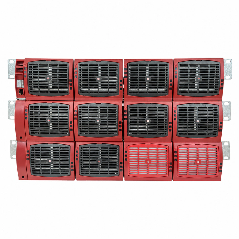
Delivering 3.5MW of continuous power into a compact footprint requires rethinking traditional low-voltage electrical distribution. Conventional 480V AC distribution topologies incur catastrophic $I^2R$ conduction losses, requiring thick copper cabling that restricts airflow and exceeds physical raceway volumetric capacities. Modern 3.5MW modular architectures transition immediately from medium-voltage step-down transformers (e.g., 13.8kV/34.5kV down to 415V AC or direct rectified DC) into a centralized, solid-state uninterruptible power system (UPS) topology. From this core, power is distributed down the pod aisles via 380V High-Voltage Direct Current (HVDC) or bipolar $\pm190\text{V}$ DC busway configurations, dramatically lowering conductor cross-sectional areas and slashing internal distribution losses by up to 40% relative to standard three-phase AC distribution.
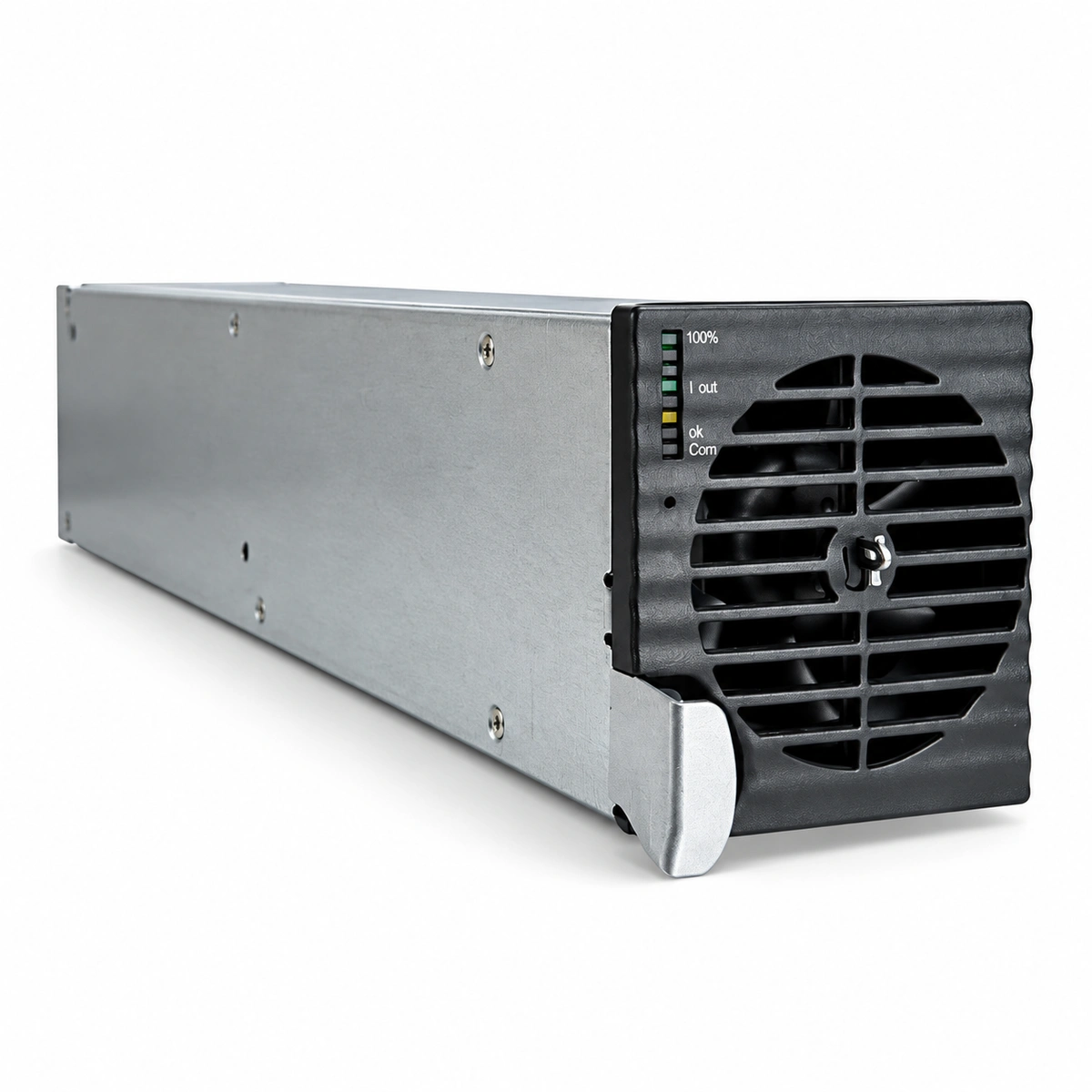
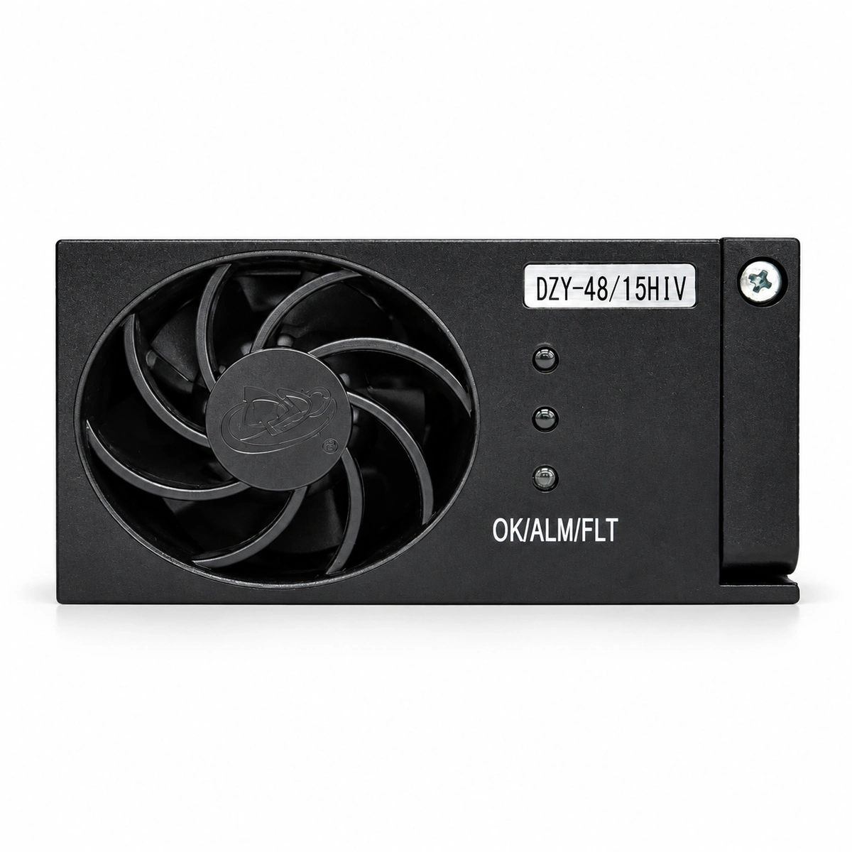
Within the compute racks, alignment with the Open Compute Project (OCP) Open Rack Standard Version 3 (ORV3) facilitates final power delivery. Highly efficient isolated DC-DC converters step down the 380V HVDC supply to a unified 48V or 54V centralized busbar integrated along the rear mechanical spine of the rack frame. Rack-level power distribution units (rPDUs) and blind-mate compute shelf connectors feed on-board multi-phase buck converters that deliver sub-1.0V core voltages directly to the silicon package at instantaneous currents exceeding 1,500A. By removing internal server-chassis power supply units (PSUs) and utilizing localized supercapacitor or lithium iron phosphate (LFP) battery backup units (BBUs) on the 48V bus, the architecture eliminates dual-conversion losses and enhances end-to-end electrical efficiency to over 96.5%.
A critical engineering challenge in high-scale AI infrastructure is the transient power dynamics associated with training workloads. Step changes in compute activity—such as shifting from gradient computation to barrier synchronization—can trigger megawatt-level load swings within milliseconds ($dI/dt$ excursions). The 3.5MW modular power block incorporates high-speed active power conditioning and centralized fast-responding capacitive banks to absorb and smooth transient voltage sags and surges. This stabilization ensures that input power parameters to the multi-phase point-of-load (PoL) regulators remain within strict IEEE 519 and ITIC design envelopes, avoiding hardware lockups or premature capacitor breakdown.
Measure total harmonic distortion (THD) at the medium-voltage transformer secondary terminals under variable 10% to 100% non-linear load conditions, verifying THD remains below 3%.
Inspect OCP ORV3 48V/54V copper busbars for coplanarity and torque tolerance on all mechanical joints using calibrated infrared thermography.
Execute dynamic step-load transient testing (20% to 100% to 20% within 5ms) to confirm the 48V bus voltage deviation does not exceed $\pm 5\%$.
Verify operational sync of distributed battery backup units (BBUs) and validate autonomous millisecond islanding during simulated grid phase failure.
Structural Engineering and Nvidia DSX POD Alignment
The physical architecture of 3.5MW modular data centers increasingly adheres to open, standardized multi-node compute references, such as the Nvidia DSX POD and OCP Modular Data Center (MDC) design specifications. This standardization imposes rigorous tolerances on spatial configurations, compute pitch, blind-mate hydraulic couplings, and structural dynamics. The structural shell typically utilizes a modified ISO high-cube frame or a proprietary interlocking steel skid manufactured with high-tensile structural steel (e.g., ASTM A572 Grade 50). The envelope features multi-layer insulated thermal-break panels providing high thermal resistance ($R\text{-value} \ge 24$) and acoustic damping to suppress interior noise emissions below 75 dBA, satisfying strict urban and industrial boundary codes.
Serviceability within a 3.5MW high-density footprint demands a disciplined physical layout. High-density designs often implement all-front-access servicing architectures or precision hot-aisle containment corridors configured to maintain strict separation between any remnant low-density air loops and primary hydraulic supply paths. Blind-mate, drip-free quick-disconnect (QD) couplings conforming to non-spill OCP mechanical standards allow individual compute blades, containing multiple liquid-cooled accelerator trays, to be hot-swapped without draining the fluid loop or releasing trace droplets onto the energized 48V busbar. Structural overhead raceways isolate signal-integrity-sensitive InfiniBand/ROCEv2 OSFP optical cabling from heavy secondary liquid lines and low-voltage DC busways.
Environmental isolation is guaranteed through an integrated building management system (BMS) that maintains positive internal atmospheric pressure using HEPA-filtered makeup air, preventing dust particulate ingress (ISO 14644-1 Class 8 or better). Integrated safety networks include fast-acting optical aspirating smoke detection (VESDA) tied to localized non-conductive gaseous fire suppression systems (e.g., FK-5-1-12/Novec 1230). In parallel, an array of continuous conductive sensing ropes located in recessed skid channels and beneath all blind-mate hydraulic junctions detects hydrocarbons or aqueous glycols, triggering automated millisecond solenoid shut-off valves to compartmentalize mechanical fluid leaks before damage can propagate.
Confirm that blind-mate hydraulic quick disconnects register zero fluid egress during minimum 50-cycle physical insertion and extraction stress testing.
Verify internal enclosure pressurization maintains a steady positive differential of +20 Pa relative to external ambient conditions.
Validate millisecond fluid isolation solenoids via simulated liquid detection on the primary manifold catchment tray.
Ensure overhead cable separation distances between 380V HVDC conduits and 800G/1.6T structured fiber trunks comply with strict EMI/EMC mitigation thresholds.
Total Cost of Ownership (TCO), Capital Velocity, and Edge Inference Economics
The operational and capital financial models for AI infrastructure diverge fundamentally from general-purpose enterprise cloud hosting. Traditional stick-built hyperscale projects require massive front-loaded capital expenditures ($500\text{M}+$) committed to multi-hundred-megawatt substations, civil campuses, and physical shells that may sit partially vacant for quarters while clusters are racked and stacked. In contrast, 3.5MW modular blocks enable modular capital expenditure (CapEx) tracking. Operators can add compute capacity in precise, discrete increments that map directly to compute cluster commitments. This approach prevents idle infrastructure debt and shifts the average project internal rate of return (IRR) curve forward by 18 to 24 months.
Operational expenditure (OpEx) optimization is driven by structural reductions in energy and maintenance overheads. By operating with high supply water temperatures ($45^\circ\text{C}$ to $55^\circ\text{C}$), the direct-to-chip liquid cooling loop operates in dry-cooler economizer mode across nearly all global ASHRAE climate zones, avoiding the energy costs of mechanical chillers. This mechanical efficiency delivers an annual average PUE of less than 1.15, reducing cooling parasitic energy loads to under 13% of total facility consumption, down from the 30% to 40% typical of conventional air-cooled facilities. Over a standard 5-year compute lifecycle, a 3.5MW modular block saves millions of dollars in net utility costs while delivering higher silicon availability via stabilized, reduced junction temperatures.
Beyond hyperscale campuses, the 3.5MW form factor functions as an ideal, self-contained compute engine for distributed inference and regional 'Sovereign AI' initiatives. National regulatory frameworks and localized data protection mandates increasingly require foundational model retraining and inference on local geographic data, away from centralized cloud campuses. Because a 3.5MW modular unit requires only a bare concrete pad, a medium-voltage electrical interconnect, and a closed-loop secondary cooler, it can be deployed at industrial enterprise sites, adjacent to municipal substations, or behind-the-meter alongside dedicated alternative energy sources like natural gas microturbines, hydrogen fuel cells, or small modular reactors (SMRs).
Audit lifecycle TCO calculations to ensure levelized cost of compute (LCOC) accounts for an operational PUE $\le 1.15$ alongside regional cost-of-water avoidance savings.
Model behind-the-meter generation integration scenarios to confirm power factor compatibility and calculate fuel-to-token thermal efficiency.
Evaluate regional sovereign data protection compliance protocols for physical enclosure access controls, biometrics, and audit logging.
Validate microgrid controller synchronization speeds during seamless transitions between grid-tied operation and on-site generation sources.
Commissioning Protocols, Factory Acceptance Testing (FAT), and Field Hookup
The operational reliability of high-density modular data centers depends on testing rigor at the factory. Traditional field commissioning (Levels 1 through 5) is frequently plagued by adverse weather conditions, missing components, and complex multi-contractor handoffs. The modular approach transfers up to Level 4 commissioning entirely to the factory floor. During Factory Acceptance Testing (FAT), each 3.5MW pod undergoes a full thermal and electrical burn-in using integrated resistance load banks that emulate dynamic GPU power and heat profiles. Liquid cooling loops are filled, degassed, and subjected to automated thermal transients, verifying that CDUs, variable-frequency drives (VFDs), and control loop PID coefficients maintain exact setpoints under full operational loading.
Hydraulic integrity assurance requires testing protocols that exceed conventional field standards. Prior to factory sign-off, internal liquid networks undergo dual-stage integrity testing: first, an ultra-sensitive helium mass spectrometer vacuum decay test capable of detecting micro-fissures down to $10^{-6}\,\text{mbar}\cdot\text{l}/\text{s}$, followed by hydrostatic pressure testing at 1.5 times nominal working pressure (typically 12 to 15 bar) sustained for a minimum of 24 hours. Once verified, the loops are drained, flushed with dry nitrogen, and sealed under positive nitrogen pressure for transport. This process eliminates internal oxidative corrosion during logistics and guarantees the mechanical integrity of every junction upon field delivery.
Site deployment follows a standardized field hookup protocol designed to minimize on-site operational time. Upon arrival via standard heavy-haul flatbeds, the 3.5MW pod is rigged onto a leveled concrete foundation pad using integrated lifting lugs or hydraulic jacking systems. Site technicians execute four standardized physical connections: primary medium-voltage AC or 380V HVDC busway flanges, pre-terminated MPO/MTP structured fiber-optic backbone trunks, secondary closed-loop fluid supply/return victaulic mechanical couplings, and external building management system (BMS) communications. Field Level 5 integrated systems testing (IST) is completed within 7 to 14 days, accelerating site readiness into a rapid plug-and-play operation.
Verify factory helium leak testing certificates confirm zero leakage exceeding $1\times 10^{-6}\,\text{mbar}\cdot\text{l}/\text{s}$ across all primary cooling circuits.
Inspect shipping shock and tilt data-loggers upon transport delivery to verify maximum G-force shock parameters were not exceeded during transit.
Execute automated field hydro-test at 1.25x working pressure for 4 hours following field connection of secondary fluid loop couplings.
Complete automated end-to-end telemetry mapping to the central BMS platform, verifying 100% telemetry resolution for all CDU sensors, rack flow meters, and circuit monitor points.
Engineering Procurement & Technical Desk
For technical datasheets, custom power topology design, or volume export quotations, reach out to HEFENGQI engineers.