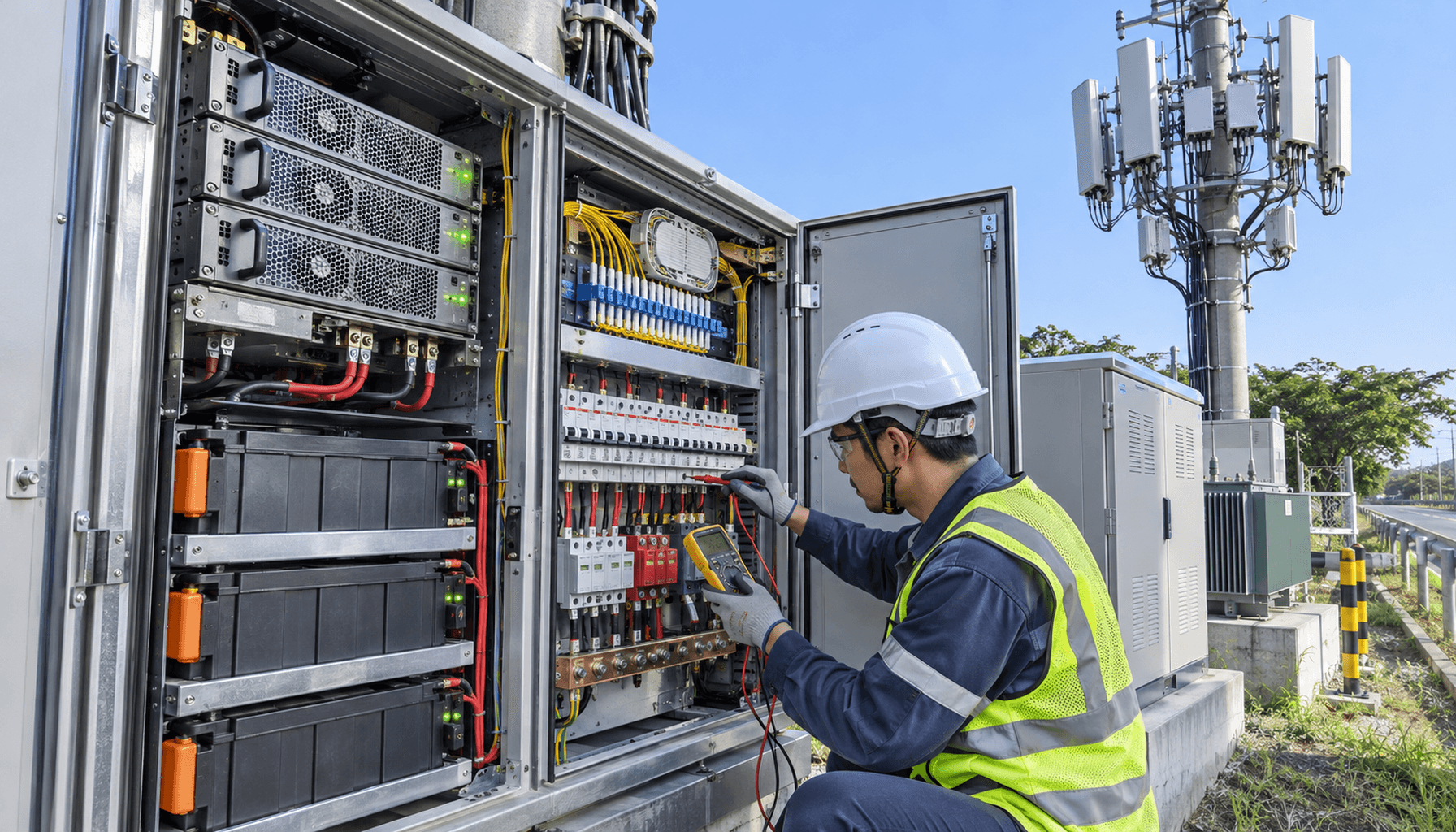
1. Next-Generation Outdoor Rectifier Topologies & Wide Bandgap (GaN/SiC) Conversion Efficiency
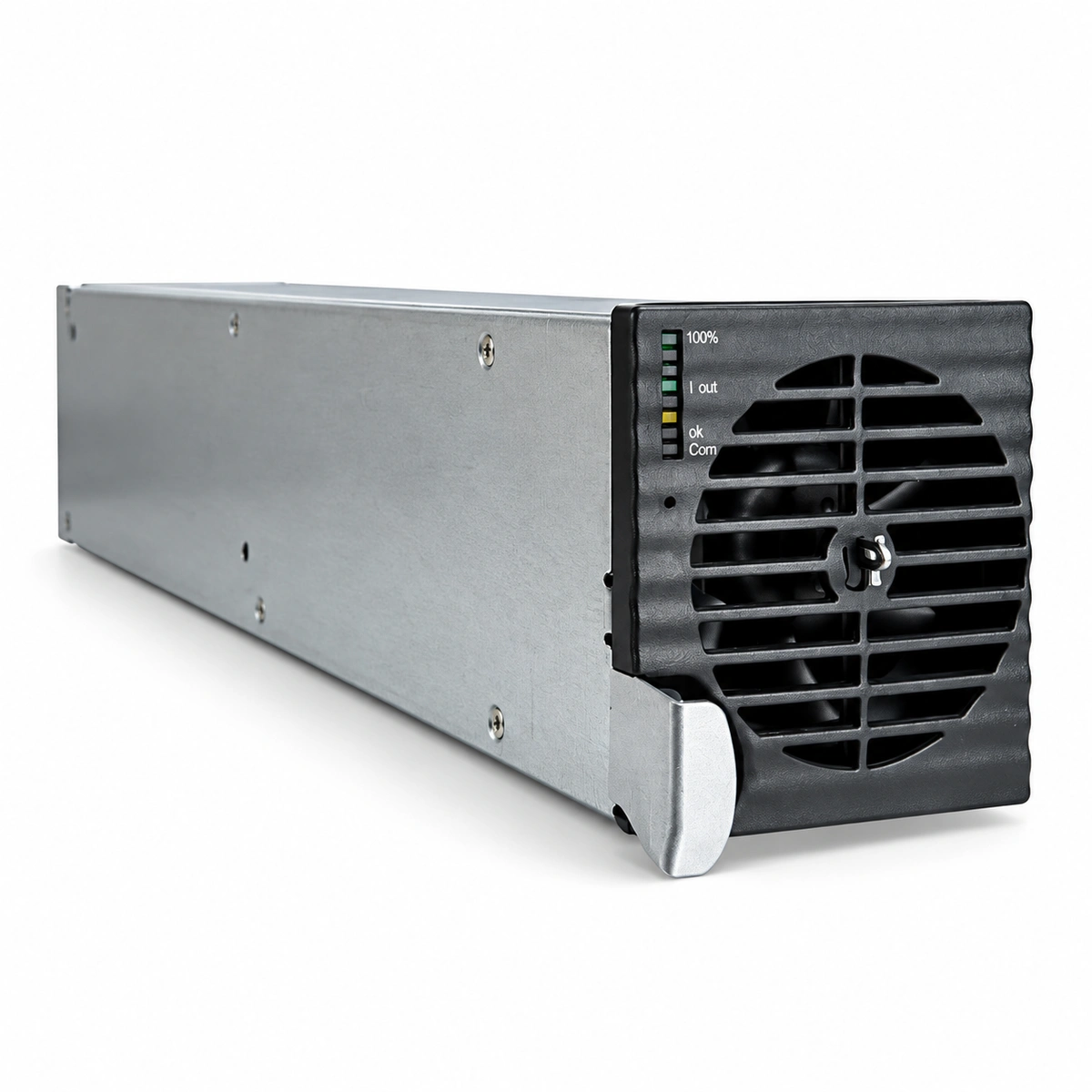
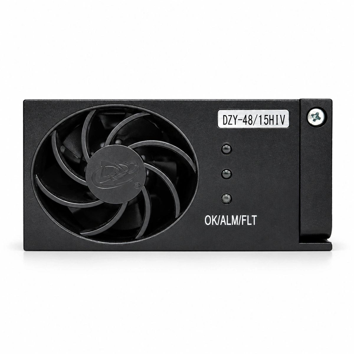
The densification of 5G-Advanced (5G-A) networks and the architectural consolidation of centralized baseband units (BBU/DU pools) within Cloud Radio Access Networks (C-RAN) have rendered traditional indoor macro power enclosures obsolete for edge aggregation. The physical distribution of remote radio units (RRUs) and high-power 64T64R active antenna units (AAUs)—often demanding instantaneous peak loads exceeding 1,800 W to 2,400 W per sector—requires zero-footprint distributed power conversion at the pole or wall edge. Conventional Silicon (Si) superjunction MOSFET-based rectifiers fall short under these thermal and spatial constraints due to reverse recovery losses and low switching frequencies (typically capped under 80 kHz). Modern 2026 micro-power designs utilize bridgeless totem-pole power factor correction (PFC) stages cascaded into isolated LLC resonant DC/DC converters, driven by Gallium Nitride (GaN) high-electron-mobility transistors (HEMTs) on the primary side and Silicon Carbide (SiC) Schottky barrier diodes or low-Rds(on) SiC MOSFETs on the synchronous rectification secondary side. Operating switching frequencies are elevated to 250 kHz–500 kHz, substantially shrinking the magnetic volume of planar high-frequency transformers while reducing input total harmonic distortion (THD) below 2.5% across a 20% to 100% loading profile.
Electrical performance criteria for these C-RAN outdoor power units mandate an ultra-wide AC input range spanning 85 V AC to 300 V AC to tolerate unstable, rural, or edge-of-grid utility feeds. Active PFC circuits achieve a power factor (PF) greater than 0.995 from 50% to 100% of rated load, minimizing reactive power penalties from grid operators. Conversion efficiency profiles represent a crucial thermodynamic constraint: modern GaN/SiC topologies achieve peak efficiencies exceeding 98.4% at nominal 230 V AC input and 50% loading, maintaining a flat efficiency profile greater than 96.8% down to 15% load. The DC output is electronically regulated across a continuous -42 V DC to -58 V DC rail. A critical feature in modern 5G-A micro-rectifiers is autonomous dynamic output voltage adjustment; during high-traffic load states, the rectifier boosts nominal output from -48 V DC up to -57.5 V DC. This 9.5 V headroom compensation directly counteracts ohmic line losses ($I^2R$) across long 10 mm² to 16 mm² DC feeder cables running up to 120 meters up tower masts, ensuring the remote AAU terminals never experience undervoltage trip conditions (typically -38 V DC to -40 V DC dropouts) during maximum beamforming transmission bursts.
Thermodynamic design without active forced-air cooling is an absolute operational requirement to eliminate fan failure vectors and filter clogging in unconditioned outdoor environments. Rectifiers are encased in high-grade die-cast aluminum (ADC12) housings rated to ingress protection standards IP65 or IP66, relying exclusively on natural convection and passive radiation. Heat-generating power semiconductors are directly bonded via high-thermal-conductivity ceramic substrates (Direct Bonded Copper with AlN or Si3N4, thermal conductivity >180 W/m·K) to internal heat-spreading vapor chambers that interface with exterior high-aspect-ratio longitudinal cooling fins. The resulting thermal resistance junction-to-ambient ($R_{\theta JA}$) is engineered to be less than 0.35 °C/W. This enables sustained, non-derated power delivery up to 3.0 kW to 4.0 kW per modular power blade across ambient operating temperatures spanning -40 °C to +55 °C, with a derated operational threshold extending to +65 °C. Calculated Mean Time Between Failures (MTBF) under Telcordia SR-332 Issue 4 specifications exceeds 500,000 operational hours at a continuous +40 °C ambient profile.
Verify input current THD < 3.0% and Power Factor > 0.99 across 30% to 100% rated load using a calibrated 3-phase/1-phase precision power analyzer.
Perform step-load transient response testing: verify output voltage returns to within ±1.0% of nominal setpoint within 200 microseconds following a 10% to 90% load step.
Execute dynamic voltage boost verification: confirm automated ramp to -57.0 V DC (±0.5 V) upon detection of secondary output current exceeding 80% threshold.
Inspect IP66 chassis thermal distribution using calibrated long-wave infrared (LWIR) thermography under full 4.0 kW load at +45 °C ambient; ensure maximum enclosure temperature rise does not exceed 30 °C above ambient.
2. Pole-Mounted LiFePO4 Energy Storage Systems: Cell Chemistry, Thermal Management, and BMS Architecture
Electrochemical energy storage for distributed 5G-A C-RAN nodes demands the total replacement of legacy Valve-Regulated Lead-Acid (VRLA) and Nickel-Cadmium batteries with specialized pole-mountable Lithium Iron Phosphate (LiFePO4 / LFP) packs. LFP chemistry offers intrinsically stable phospho-olivine crystal structures that eliminate the risk of thermal runaway up to 270 °C, providing an indispensable safety margin for elevated urban pole mounts. Standard packaging leverages 15S or 16S prismatic cell topologies (delivering nominal 48.0 V or 51.2 V systems) with typical capacities ranging from 50 Ah to 100 Ah per modular 3U/4U casing. The electrochemical performance envelope guarantees greater than 5,000 cycles to 80% state-of-health (SoH) at 25 °C under a 0.5C charge / 1.0C discharge regime at 80% Depth of Discharge (DoD), and retains >3,500 cycles even under elevated 45 °C cyclic aging. Continuous discharge ratings are specified up to 1.5C (150 A for a 100 Ah pack) with peak pulse capabilities up to 2.5C for 30-second intervals to accommodate simultaneous traffic-channel scheduling peaks across co-located massive MIMO arrays.
Thermal control within fully sealed, pole-mounted enclosures subjected to direct solar irradiance (up to 1,120 W/m² pursuant to IEC 60068-2-5) requires a combined passive-barrier and active-heating strategy. Cell matrices are insulated from exterior casing walls via micro-porous silica aerogel blankets (thermal conductivity <0.018 W/m·K) and Phase Change Material (PCM) heat sinks that absorb peak daytime thermal spikes, dampening the diurnal cell temperature swing to within a Δ12 °C envelope. For sub-zero operations, charging lithium iron phosphate below 0 °C is chemically precluded to prevent irreversible lithium dendrite plating and catastrophic internal short circuits. Therefore, integrated Smart BMS architectures implement internal 48 V DC positive temperature coefficient (PTC) flexible silicone heating mats. Upon detecting sub-zero temperatures (-40 °C to 0 °C) via multiple cell-embedded NTC thermistors, incoming rectifier power is fully diverted to pre-heat the cell core matrix at a rate of 1.5 °C/minute. Rectifier-to-battery charging circuits remain hardware-isolated via solid-state switches until all cell cores reach a uniform minimum threshold of +5 °C.
The integrated Smart Battery Management System (BMS) executes multi-tier telemetry and protection functions via industrial-grade microcontrollers with hardware-accelerated floating-point units. Telemetry acquisition engines sample individual cell voltages to an accuracy of ±2 mV and temperatures to ±0.5 °C at 100 Hz sampling intervals. State of Charge (SoC) and State of Health (SoH) estimation departs from primitive open-circuit voltage lookups and ampere-hour dead reckoning, implementing instead high-fidelity Dual Extended Kalman Filtering (DEKF) that factors in instantaneous internal electrochemical impedance spectroscopy (EIS) parameters. Cell balancing is achieved via bi-directional active inductive or capacitive shuttle topologies capable of shifting balancing currents up to 2.0 A between adjacent cells, vastly outperforming legacy passive resistor bleed-off topologies that introduce unacceptable localized parasitic heat inside IP65 sealed enclosures. Redundant hardware protection switches (dual bi-directional back-to-back MOSFET arrays or high-current bistable latching contactors) decouple the pack within 10 microseconds under short-circuit detection thresholds exceeding 1,200 A.
Validate cell-level over-voltage, under-voltage, and over-temperature safety cut-off limits across all 15S/16S channels using automated secondary injection test sets.
Verify sub-zero cold-soak heating sequence: inject -25 °C environment, confirm charging lockout, and measure PTC heater ramp rate to +5 °C before main charge contactor closure.
Measure active cell balancing current during continuous float-charge stage: ensure active transfer current exceeds 1.5 A when an artificial 50 mV cell imbalance is induced.
Perform high-current transient discharge test: drive pack to 2.0C for 30 seconds; verify total terminal voltage droop remains below 2.8 V and BMS maintains full telemetry reporting over CAN bus.
3. Smart Peak Shaving Algorithms, Grid-Interactive Demand Response, and Mains Augmentation
The massive power divergence inherent to 5G-Advanced C-RAN deployments creates severe infrastructure bottlenecks at the grid interconnection point. While idle power for an entire 3-sector C-RAN aggregation site may dip to 800 W during night hours (02:00–05:00), busy-hour traffic surges involving high-order multi-user MIMO (MU-MIMO) beamforming, carrier aggregation, and edge computing workloads drive instantaneous site power consumption to spikes between 3,500 W and 5,000 W. In many urban and suburban pole locations, upgrading the local low-voltage utility distribution transformer or drop line to support 5 kW peak capacities is cost-prohibitive or physically unviable due to utility regulatory delays. The micro-power system must therefore function as an active mains augmentation and power-smoothing device. The centralized power management unit (PMU) tracks real-time AC input power via true-RMS current transducers and continuously evaluates utility line strain against programmable peak-shaving thresholds (e.g., hard-capping AC grid draw at 1,500 VA).
The algorithmic execution of smart peak shaving leverages microsecond-level coordinated control loops between the active GaN rectifiers and the bi-directional DC/DC battery interface. When site power demand exceeds the pre-set grid consumption ceiling, the rectifier output is rapidly throttled to maintain constant grid draw, and the BMS transitions the LiFePO4 battery pack from float mode to active parallel discharge mode without introducing phase or bus voltage transients. Response times for the current-sharing dispatch loop are maintained under 5 milliseconds, well within the holdup time of the rectifier output capacitor bank (typically >15 ms at full load). The battery injects the exact delta current required by the baseband and radio units. Conversely, during low-traffic periods when site demand falls below the grid limit, the control system dynamically utilizes the surplus grid capacity to recharge the battery system at controlled 0.2C to 0.5C rates. This effectively shifts the grid load profile from a highly peaky distribution to an almost flat, predictable baseload curve.
At the macro grid scale, the integration of 5G-A micro-power fleets into unified Virtual Power Plants (VPPs) unlocks revenue-generating demand response capabilities for telecom operators. Utilizing open-standard machine-to-machine telemetry protocols such as OpenADR 2.0b alongside northbound SNMPv3 or secure MQTT over TLS 1.3, the carrier's operations support system (OSS) can execute coordinated peak-clipping or valley-filling requests across tens of thousands of distributed pole sites simultaneously. To maintain uncompromising telecommunications availability during grid events, the PMU firmware enforces a deterministic "Dynamic Reserve Capacity" algorithm. This algorithm continuously queries cell SoH, historical weather patterns, and local grid reliability indexes to dynamically partition the LiFePO4 storage capacity into two distinct logical segments: a non-negotiable Emergency Reserve Tier (typically 30% to 50% SoC strictly reserved to cover full utility outages according to SLA mandates) and a flexible Peak Shaving / Energy Arbitrage Tier (the upper 50% to 70% SoC utilized for economic grid interaction).
Execute automated peak-shaving validation: limit AC mains draw to 2,000 W, step DC system load from 1,500 W to 4,200 W within 10 ms, and verify grid draw does not exceed 2,000 W ± 2%.
Verify Dynamic Reserve Capacity lockout: confirm battery peak-shaving discharge terminates cleanly when pack drops to the configured 35% SoC reserve floor.
Measure seamless transition times between Mains-Only, Mains-Plus-Battery, and Battery-Only modes using a high-speed digital storage oscilloscope (DSO); verify DC rail ripple remains <200 mVp-p.
Simulate an OpenADR 2.0b demand response event via secure northbound MQTT; ensure the micro-power system ramps discharge within 500 ms and logs accurate energy accounting telemetry.
4. System Integration, Busbar Dynamics, Cable Ohmic Loss Mitigation, and Edge Observability
Mechanical and electrical integration within compact outdoor micro-power enclosures demands uncompromising attention to conductor sizing, structural impedance, and overcurrent protection coordination. Within a typical volume of under 45 liters, the DC distribution architecture must route up to 100 A continuous load currents while withstanding prospective short-circuit currents exceeding 10 kA from combined rectifier capacitors and ultra-low-impedance LiFePO4 modules. DC busbars are engineered from solid Electrolytic Tough Pitch (ETP) Copper (C11000, 99.9% IACS conductivity), electro-tin plated to an 8–10 µm thickness to prevent galvanic corrosion and contact resistance creep over a 15-year operational lifecycle. Busbar cross-sectional areas are strictly maintained at or above 30 mm² to keep temperature rises below 20 °C under maximum continuous loading. Overcurrent protection relies on fast-acting, high-interrupting-capacity DC semiconductor fuses (aR/gR characteristics) or specialized high-speed magnetic-hydraulic circuit breakers, completely isolating short circuits within 3 to 5 milliseconds to prevent busbar vaporization and arc-flash escalation.
Mitigation of cable ohmic loss ($I^2R$) across the DC distribution trunking represents a foundational engineering challenge on 5G-A tall towers and dense C-RAN fiber-to-the-antenna (FTTA) topologies. Supplying a three-sector 64T64R AAU cluster over 80 meters of conventional 10 mm² copper conductor at nominal -48 V DC results in line impedances of approximately 0.288 Ω round-trip. At peak draw (e.g., 45 A total draw), this produces a 13.0 V line drop, plunging the terminal voltage at the remote radio heads to -35.0 V DC and triggering catastrophic undervoltage shutdowns. The distributed micro-power system resolves this via its closed-loop programmable dynamic boost converter stage, which automatically scales terminal output voltage from -48.0 V DC up to -57.5 V DC proportionally to the measured load current. By forcing higher voltage and lower current across the DC feed run, ohmic transmission losses are reduced by up to 30.5% (calculated via $P_{loss} = I^2R$), preserving terminal voltages above -44.5 V DC at the AAU interface without requiring expensive, heavy, and wind-load-inducing 25 mm² or 35 mm² cable upgrades.
Edge observability, environmental durability, and operational survivability must be engineered to withstand two decades of field exposure without on-site manual intervention. Enclosure chassis are fitted with ePTFE hydrophobic and oleophobic breathable venting membranes (Gore vents), equalizing internal and external pressure differentials caused by rapid solar-induced thermal cycling while maintaining complete IP66 hermetic protection against wind-driven torrential rain and salt-fog atmospheres (tested per IEC 60068-2-52 severity 5). Communication and control engines feature isolated physical layers, including dual galvanic-isolated CAN 2.0B buses (for real-time intra-module rectifier, BMS, and PMU synchronization) and dual RS-485 interfaces running Modbus RTU. Northbound connectivity is established through an integrated industrial edge controller communicating via Ethernet (10/100/1000Base-T) or integrated 5G sub-6 GHz low-power modems. Edge telemetry packets deliver full diagnostic traces—including individual cell electrochemical impedances, real-time AC grid waveform distortion, instantaneous thermal heat map vectors, and surge protective device (SPD) life status—to centralized telecom OSS platforms via encrypted SNMPv3 and Zero-Trust architecture.
Perform DC busbar contact resistance profiling: verify resistance across all bolted connections and fuse holders is <15 micro-ohms using a 100 A micro-ohmmeter (DLRO).
Validate cable loss mitigation circuitry: under a full-scale 50 A simulated load bank through an artificial 0.30-ohm line simulator, verify terminal end voltage remains >-45.0 V DC during -57.5 V DC boost activation.
Test Lightning Surge Protective Device (SPD) coordination: confirm Class I / Class II SPD clamping voltage performance meets IEC 61643-11 specifications for 20 kA (8/20 µs) discharge currents without controller telemetry interruption.
Verify dual-isolated CAN 2.0B / RS-485 physical bus isolation: ensure >1.5 kV AC dielectric isolation between signal grounds and the high-current DC power bus using a high-potential (Hi-Pot) tester.
Engineering Procurement & Technical Desk
For technical datasheets, custom power topology design, or volume export quotations, reach out to HEFENGQI engineers.