LEO Gateway Ground Station Evolution: The Bercenay-en-Othe Architectural Transition
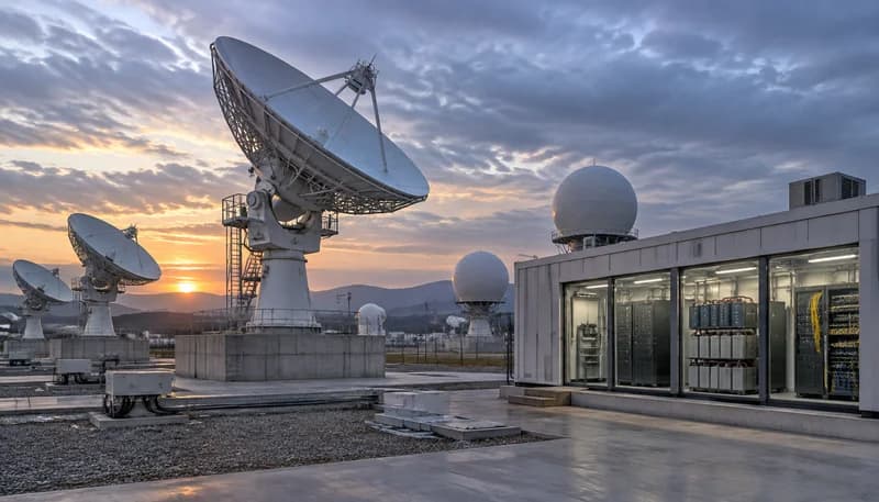
According to a Light Reading industry report by Michelle Donegan, Orange has commissioned the first European gateway for Telesat's Lightspeed Low Earth Orbit (LEO) constellation at its historical teleport in Bercenay-en-Othe, France, located approximately 100 miles from Paris. To accommodate the new constellation infrastructure, Orange dismantled a legacy 32-meter geostationary Earth orbit (GEO) antenna and replaced it with ten tracking antennas measuring between 1 and 4 meters in height. Operating within an electro-magnetically quiet rural environment suitable for full orbital visibility, the site directly interfaces with Telesat's planned 225-satellite constellation ahead of its targeted early 2028 commercial service launch. The gateway connects directly into a mission-critical terrestrial point of presence (PoP) in Paris via high-capacity fiber.
The shift from monolithic GEO dishes to distributed clusters of tracking antennas fundamentally reshapes teleport infrastructure engineering. Unlike fixed GEO reflectors that maintain static pointing vectors, Telesat Lightspeed utilizes optical inter-satellite links (ISLs) to route sovereign data in space, requiring ground gateways to execute continuous handovers across multiple dynamic satellites. Light Reading notes that Bercenay-en-Othe is operated by an Orange satellite engineering unit of 100 specialists, with 25 dedicated to site antenna operations. From a power and physical plant perspective, replacing one giant static drive with ten agile motorized tracking pedestals transforms the ground station load profile from a predictable continuous draw into a highly dynamic, distributed power architecture requiring robust power delivery and minimal systemic noise.
Audit existing teleport footprint and decommission legacy high-voltage GEO tracking infrastructure to make way for multi-pedestal arrays.
Establish low-latency, diverse terrestrial backhaul links to core urban points of presence to match LEO constellation throughput.
Verify local radio frequency interference (RFI) profiles and clear line-of-sight elevation angles across the horizon for continuous orbital tracking.
Teleport Ground Station DC Power Topography: Redundant A/B Distribution and Dynamic Pedestal Drives
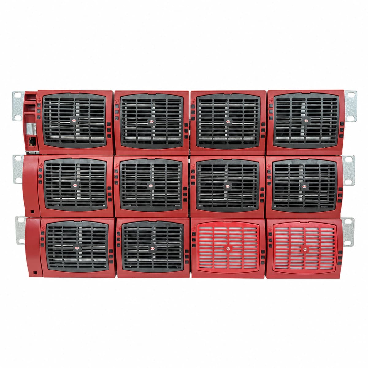
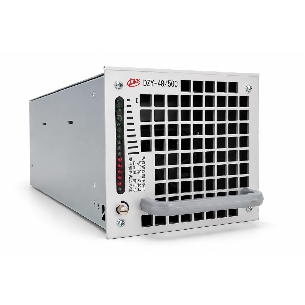
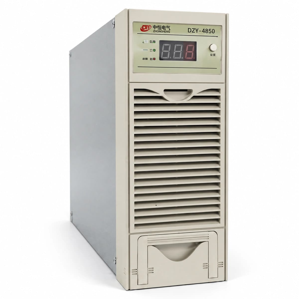
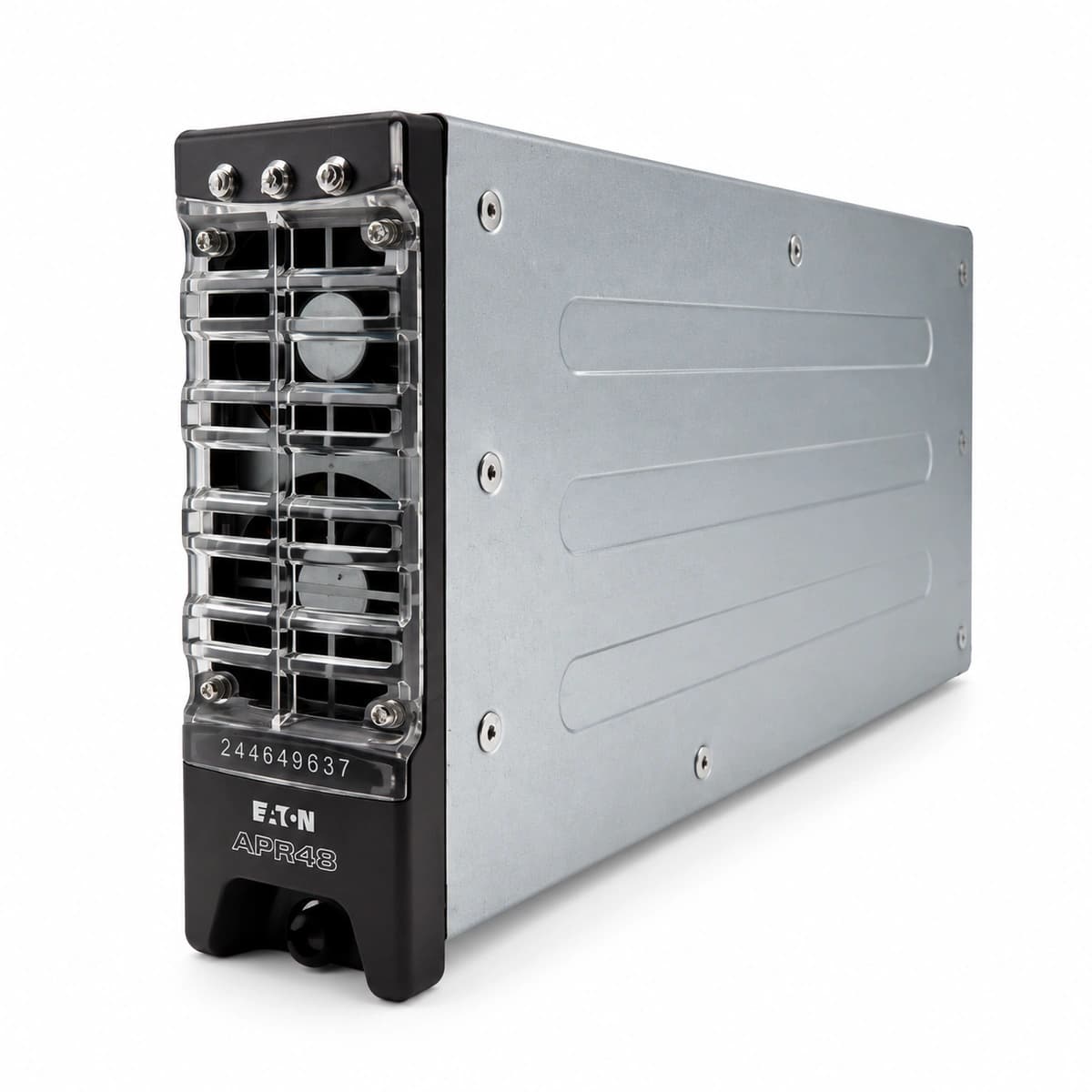
Modern LEO teleport designs demand a carrier-grade -48V DC power architecture that guarantees 99.999% availability while handling simultaneous steady-state and dynamic transient loads. A centralized power plant topology utilizes dual independent AC-to-DC switched-mode rectifier racks configured in an N+M redundancy scheme (typically N+2 for remote teleports). Rectifier shelves convert three-phase 400V AC utility power into a regulated -54.0V float bus (delivering nominal -48V DC across distribution runs). Power distribution units (PDUs) separate critical communication hardware—such as baseband optical modems, software-defined radio (SDR) transceivers, and solid-state power amplifiers (SSPAs)—from pedestal motion control subsystems across distinct A/B dual-bus paths.
Distributed tracking antennas (1 to 4 meters) introduce dynamic mechanical and electrical stresses. Pedestal azimuth and elevation drives employ brushless DC (BLDC) or stepper servo motors that draw sharp pulse-currents during rapid satellite acquisition and slew maneuvers (exceeding 15 degrees per second during horizon handovers). To prevent these motor current spikes and inductive back-EMF from coupling onto the sensitive RF transceiver rails, the DC distribution architecture must decouple motor power feeds using localized DC-DC isolation converters and dedicated LC filtering networks. Power cable cross-sectional area (A) must be mathematically sized to enforce a maximum loop voltage drop under 2% over long trench runs (typically 50 to 150 meters) using the formula A = (2 * L * I * ρ) / V_drop, where ρ is the resistivity of annealed copper (1.724 x 10^-8 Ω·m).
Segregate DC distribution paths into distinct A/B buses with separate circuit breaker trip curves: Class C/D for motor pedestals and Class B for RF/modem electronics.
Incorporate localized LC ripple-attenuation filters and freewheeling flyback clamp diodes at each antenna pedestal power entry point.
Calculate cable sizing based on worst-case concurrent slewing inrush current rather than nominal continuous thermal ratings.
Battery Autonomy and Outdoor Environmental Resilience: LiFePO4 Chemistry Under High-Duty Cycles
LEO ground gateways operate under severe thermal and operational duty cycles that render traditional Valve-Regulated Lead-Acid (VRLA) batteries obsolete. Lithium Iron Phosphate (LiFePO4) chemistry has emerged as the standard for teleport backup systems due to its superior cycle life (4,000 to 6,000 cycles at 80% Depth of Discharge), rapid charge acceptance rates (0.5C to 1C versus 0.1C for VRLA), and volumetric energy density. Gateway power design requires sufficient battery autonomy to sustain full-load tracking and transmission during utility power failures while an on-site automatic transfer switch (ATS) initiates and synchronizes dual diesel generators (typically requiring 15 to 45 seconds to achieve stable voltage and frequency lock).
Environmental engineering becomes critical when battery enclosures and distributed rectifiers are deployed outdoors adjacent to radomes across temperature regimes spanning -40°C to +55°C. At sub-zero temperatures, standard lithium-ion charging produces lithium plating, resulting in permanent capacity loss and internal short-circuits. Telecom-grade outdoor LiFePO4 battery modules must therefore integrate an intelligent Battery Management System (BMS) with internal positive temperature coefficient (PTC) heating blankets. The BMS automatically diverts float energy to warm cells to at least +5°C prior to enabling charge current acceptance, while active forced-air or closed-loop liquid cooling manages thermal runaway risks during high-ambient heatwaves.
Specify LiFePO4 battery strings equipped with autonomous internal heating elements and multi-tier CAN/Modbus BMS reporting.
Calibrate automatic generator starting (AGS) thresholds to engage gensets at 75% State of Charge (SOC) to preserve reserve capacity for extended outages.
Implement thermal compartmentalization between power electronic rectifiers and battery cells inside outdoor equipment cabinets.
Lightning Surge Protection, RF Isolation, and Equipotential Grounding Coordination
Teleport antenna fields present severe lightning exposure profiles due to wide open-field positioning and elevated metallic tracking structures. Protection requires an integrated equipotential grounding system centered around a Master Ground Bar (MGB) connected to a buried perimeter ground loop (minimum 70 mm² bare stranded copper) interconnected with copper-clad steel earth electrodes, targeting a combined ground impedance below 5 Ohms (and ideally <1 Ohm for co-located core data centers). Each antenna pedestal must feature dual, direct bonding conductors connected to the ground ring to dissipate strike energy before it penetrates internal wiring conduit.
Surge protection devices (SPDs) must be deployed in a coordinated, multi-stage cascade. At the outdoor antenna pedestal base, heavy-duty Type 1 SPDs rated for direct lightning impulse current (10/350 µs waveform, minimum 25 kA per pole) clamp primary high-energy surges. Downstream at the RF shelter and internal -48V DC distribution panel boards, fast-acting Type 2 SPDs utilizing high-energy metal oxide varistors (MOVs) and silicon avalanche diodes (SADs) clamp residual overvoltages to safe operational levels (<150V). Galvanic isolation transformers and high-rejection common-mode chokes must isolate motorized drives from high-frequency Block Upconverters (BUCs) and SSPAs, preventing motor switching noise from degrading phase noise characteristics in Ka-band and Q/V-band up/down converters.
Bond all metallic antenna structures, radome rings, and cable raceways directly to the buried earth ring using exothermic welds or irreversible compression lugs.
Install coordinated Type 1 (10/350 µs) and Type 2 (8/20 µs) surge protective devices on all DC power runs entering outdoor pedestals and indoor shelters.
Ensure full galvanic separation between motor drive grounds and sensitive L-band / optical transceiver shielding to prevent circulating ground loops.
Teleport Power Telemetry, Remote Network Management, and Live Maintenance Protocols
Continuous satellite connectivity across 24 planned global gateways leaves zero tolerance for unplanned power outages. Next-generation teleport DC systems integrate comprehensive out-of-band management protocols, leveraging encrypted SNMPv3 and Modbus-TCP over secure VLANs to stream operational telemetry directly to the carrier's Centralized Network Operations Center (NOC). Parameters monitored in real time include per-branch DC current consumption, rectifier thermal efficiency, individual cell voltages, BMS internal resistance, and SPD cartridge mechanical integrity flags. Anomalies in motor slew current draw can instantly alert operators to mechanical pedestal binding or gear wear long before functional failure occurs.
Zero-downtime maintenance procedures require hot-swappable modular rectifiers and live-battery testing capabilities. Rectifiers must feature blind-mate backplane connections that permit insertion and extraction under full load without introducing voltage transients greater than ±0.5V onto the -48V bus. Routine battery discharge validation is executed through automated on-line battery test routines: the system dynamically reduces rectifier float voltage slightly below the battery open-circuit voltage, allowing the battery to support the live operational load for a calibrated duration while precision instrumentation evaluates voltage sag rates and individual cell electrochemical impedance spectroscopy (EIS) parameters without risking ground station off-line events.
Deploy branch-level DC current monitoring to track operational degradation across individual tracking pedestal actuators and RF amplifiers.
Enforce strict SNMPv3 authentication and SHA-256 encryption protocols on all telemetry control units and remote monitoring gateways.
Schedule autonomous, non-intrusive battery conductance and partial discharge tests during low-traffic orbital maintenance windows.
Operator Engineering Decision Framework and Site Deployment Roadmap
Engineering teams retrofitting legacy GEO sites or executing greenfield deployments for modern LEO constellations must follow a systematic, phased deployment framework. Initial design begins with a comprehensive dynamic load calculation: sizing rectifier arrays to handle maximum concurrent slewing power demands across all antennas simultaneously while maintaining complete N+2 redundancy. Civil and electrical infrastructure works must route low-loss DC feeders, armored grounding backbones, and optical telemetry fibers through isolated sub-grade conduits separated by at least 300 mm to avoid electromagnetic cross-coupling. Commissioning encompasses high-potential (Hi-Pot) insulation testing, grounding impedance verification via the four-point fall-of-potential method, and simulated full-load black-start transitions.
For engineered telecommunications power solutions, customized -48V DC power plants, ruggedized outdoor enclosures, and advanced lithium battery storage systems designed for high-availability satellite ground stations, consult the power engineering specialists at RICEWIND. Visit ricewind.com, contact our technical team via email at lee@ricewind.com, or reach out via WhatsApp at +86 17621197907 for dedicated architecture review and equipment engineering support.
Execute comprehensive four-point soil resistivity and fall-of-potential grounding resistance tests across the entire antenna grid prior to installation.
Perform dynamic step-load testing (0% to 100% load variations) on the -48V DC bus to ensure voltage stability during coordinated antenna array slew maneuvers.
Finalize end-to-end integration of power telemetry alerts into central network operations management systems prior to satellite constellation orbital commissioning.
Engineering Procurement & Technical Desk
For technical datasheets, custom power topology design, or volume export quotations, reach out to HEFENGQI engineers.