The Massive MIMO Power Wall and -48V DC Cable Sizing Crisis at Tower Sites
The shift from passive antennas driven by remote radio heads (RRHs) to Active Antenna Units (AAUs) employing 64T64R and 128T128R Massive MIMO configurations has fundamentally transformed macro base station power profiles. A modern tri-sector 5G-Advanced macro configuration operating across mid-band spectrum (e.g., 3.5 GHz and 2.6 GHz) demands continuous operational power between 1,200W and 2,000W per sector under full radio frequency (RF) load. When co-located with legacy 4G LTE systems and expanded to 6-sector configurations, peak power demands at the masthead reach 6kW to 12kW. Delivering these power levels via legacy -48V DC nominal bus architectures reveals severe structural limitations governed by Ohm's Law and conductor thermodynamics.
Under -48V DC distribution over typical tower elevations ranging from 60m to 120m, the total current required to sustain a 10kW load approaches 208A. The terminal operating voltage at the AAU must remain strictly within standard ETSI EN 300 132-2 tolerances, which set the lower operational limit at -40.5V DC, with commercial hardware recommending a minimum threshold of -44V DC to avoid undervoltage trip events during traffic bursts. Calculating the required copper conductor cross-section (A = (2 * L * I * ρ) / ΔV, where ρ is the resistivity of copper at 1.724 x 10^-8 Ω·m) demonstrates that a 100m vertical run supporting a 4V allowable drop demands massive copper cross-sections between 50mm² and 70mm² per pole. These heavy cable bundles impose tens of kilonewtons of additional mechanical strain on tower steelwork, expand the projected wind loading profile (Cd * A) beyond permissible structural thresholds, and expose rural and suburban installations to systematic copper cable theft.
Confirm aggregate masthead AAU peak load requirements do not exceed the thermal capacity of existing vertical DC distribution runs.
Verify terminal voltage at the AAU input power flange remains above -44V DC under 100% full-traffic scheduler bursts on all sectors.
Audit structural tower mast calculations to determine if cumulative mechanical and aerodynamic wind loads from existing heavy copper bundles exceed design limits.
380V DC Remote Power Feeding (RPDC) Circuit Physics and I²R Loss Mitigation
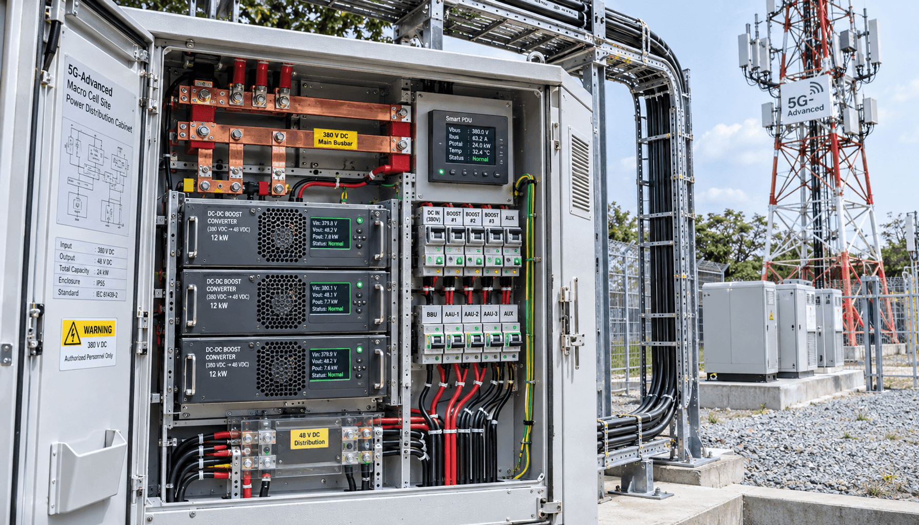
Transitioning from legacy low-voltage distribution to 380V DC Remote Power Feeding (RPDC) leverages straightforward electrical physics to circumvent low-voltage distribution bottlenecks. Power transmission losses are governed by P_loss = I² * R, where current is inversely proportional to transmission voltage (I = P / V). Stepping up the transmission potential from nominal -48V DC to 380V DC reduces current by a factor of 7.92. Consequently, for a constant conductor resistance, line I²R thermal dissipation decreases quadratically by a factor of 62.7—an over 98.4% reduction in transmission line losses under identical load conditions.
This dramatic loss reduction allows telecom civil and electrical engineers to downsize the vertical DC conductor cross-section from cumbersome 50mm²–70mm² cables to lightweight 4mm² or 6mm² twin-lead or hybrid electro-optical cables. In a Distributed Power System (DPS) topology, the ground-level embedded power plant utilizes high-efficiency isolated DC-DC boost converters (operating at 97.5% conversion efficiency) to raise the site bus voltage to 380V DC. At the masthead, compact, IP65/NEMA 4X-rated high-density buck converters step the 380V DC down to nominal -48V DC immediately adjacent to the AAUs (cable length <2m). The end-to-end electrical efficiency of the RPDC circuit typically reaches 93% to 95%, outperforming long-run -48V copper configurations suffering from continuous line-loss degradation.
Select ground-level DC-DC boost modules with certified peak conversion efficiency ratings exceeding 97.0%.
Size vertical RPDC conductors to maintain total loop voltage drop below 2.5% at nominal 380V DC across maximum cable lengths.
Ensure tower-top DC-DC step-down converters maintain an IP65 ingress rating and provide galvanic isolation between 380V distribution and -48V AAU interfaces.
Anti-Theft Economics: Eliminating Heavy Copper Incentives and Slashing Tower Wind Loads
The illicit salvage of telecom copper cable represents a multi-million-dollar operational challenge for mobile network operators globally, particularly across isolated transit corridors and peri-urban installations. Conventional -48V macro site installations present high-value targets: a 100m, six-sector site using 70mm² multi-core copper runs contains several hundred kilograms of scrap-grade unalloyed copper. Illicit removal causes extensive site outages, disrupts emergency communications, and necessitates costly emergency maintenance interventions.
Implementing a 380V DC power feeding architecture eliminates this salvage incentive at the physical level. Reducing the cross-sectional area to 4mm² or 6mm²—or utilizing Copper-Clad Aluminum (CCA) variants—drops the intrinsic metal salvage value below the break-even threshold for illicit recovery. Furthermore, the 75% to 85% reduction in total cabling mass yields substantial civil structural benefits. Reducing total cable weight from roughly 1,200kg down to under 150kg slashes dead-weight tower strain while reducing the vertical cable tray cross-sectional area, decreasing projected aerodynamic wind drag. This enables operators to deploy multi-band Massive MIMO arrays on legacy towers without performing expensive foundation and lattice retrofits, cutting vertical cabling CapEx by up to 70% and accelerating site deployment schedules by 40%.
Specify thin-gauge (4mm² or 6mm²) or copper-clad aluminum (CCA) conductors on all exposed tower ladder runs to reduce scrap metal incentives.
Re-evaluate tower structural dead-load and wind-load calculations post-cable-migration to permit installation of expanded multi-operator antenna arrays.
Track mean time between failure (MTBF) and security incident reports to quantify OpEx reductions associated with vandalism mitigation.
Electrical Safety Architecture: RFT-V / ES3 Compliance, Ground Fault Interruption (<10ms), and Arc-Fault Interlocks (<5ms)
Operating DC distribution systems at 380V shifts equipment classification into Energy Source Class 3 (ES3) under IEC 62368-1 and Remote Feeding Telecommunication circuits (RFT-V) under IEC 60950-21 and IEC 62368-3. Because DC voltages above 60V lack natural zero-crossing points, establishing robust electrical safety architectures is mandatory to protect field maintenance personnel, prevent persistent electrical arcs, and eliminate fire hazards along vertical cable ladders.
Modern RPDC systems deploy a balanced bipolar topology (±190V DC referenced to Earth ground) rather than a unipolar +380V DC or -380V DC line. This approach caps the maximum touch potential from any single energized conductor to earth at 190V, substantially lowering shock severity. Safety is reinforced through three distinct, microsecond-grade monitoring subsystems: (1) Active Ground Fault Detection (GFD), which uses high-frequency differential current sensors to sever power in less than 10ms if leakage currents exceed 10mA; (2) Active Arc Fault Circuit Interrupters (AFCI) coupled with Solid-State Disconnects (SSDC) that detect high-frequency RF noise signatures characteristic of DC series arcing and isolate circuits within 5ms; and (3) Continuous Pulse Interrogation (Open Circuit Interlock), which transmits low-energy interrogation pulses during operation. If a physical disconnect, cable cut, or connector breach occurs, the output drops to safe SELV levels (<50V DC) in under 2ms.
Validate balanced bipolar ±190V DC topology to verify maximum line-to-ground touch voltage remains below 190V under all normal operating conditions.
Calibrate high-speed Ground Fault Detection (GFD) trip thresholds to isolate supply lines in <10ms upon detecting ground leakage currents >10mA.
Verify solid-state arc fault circuit interruption (AFCI) isolates the 380V DC bus within <5ms during simulated series and parallel arcing conditions.
Ensure continuous low-energy pulse interrogation interlocks drop link voltage to SELV levels (<50V DC) within <2ms upon physical line disconnection.
Integration with Ground-Level Battery Energy Storage (Na-Ion / LiFePO4) and Solar PV Peak Shaving
The centralized 380V DC distribution architecture seamlessly integrates with modern ground-level hybrid microgrid components. Conventional macro cell sites face grid capacity constraints when Massive MIMO loads surge during peak traffic hours, often triggering upstream utility circuit breakers or incurring substantial peak-demand tariff penalties. Integrating ground-level Battery Energy Storage Systems (BESS)—specifically Lithium Iron Phosphate (LiFePO4) or high-thermal-stability Sodium-ion (Na-ion) chemistries—alongside 380V DC bus topologies provides an effective peak-shaving and backup platform.
Intelligent power controllers at the base cabinet manage bi-directional DC-DC converters interfacing with ground-level 48V battery banks. During peak RF transmission windows, the controller activates dynamic power boost routines, drawing supplemental current from the local battery reserve to satisfy the 380V masthead feed without exceeding utility grid connection thresholds. Furthermore, on-site solar photovoltaic (PV) arrays can feed directly into the 380V DC intermediate bus via Maximum Power Point Tracking (MPPT) boost regulators. This direct DC-to-DC topology avoids the double-conversion losses (DC to AC to DC) inherent in legacy solar setups, lifting solar utilization efficiency to over 96% and providing autonomous energy resiliency during utility outages.
Configure bi-directional DC-DC converters between the 48V ground battery bank and 380V DC distribution to execute dynamic peak-shaving routines.
Interface solar PV MPPT converters directly to the 380V DC intermediate bus to eliminate double-conversion inverter stages.
Program automated discharge limits on Na-ion/LiFePO4 storage to maintain adequate reserve capacity for emergency power resilience during grid outages.
Macro Site Commissioning Protocols: High-Voltage Insulation Testing (>50MΩ), Loop Resistance, and Live Cutover Guidelines
Commissioning 380V DC RPDC installations demands rigorous validation procedures to ensure electrical integrity, prevent false-positive safety trips, and maintain uninterrupted telecom services. Prior to system energization, field technicians must perform cold-state testing. This includes high-voltage insulation resistance (IR) testing using a calibrated megohmmeter applied at 1,000V DC across positive-to-ground, negative-to-ground, and positive-to-negative conductors. The insulation resistance must measure greater than 50MΩ (with ideal uncompromised cable installations exceeding 100MΩ).
Following insulation verification, precision Kelvin four-wire micro-ohmmeter testing must be conducted to establish end-to-end loop resistance, verifying crimp integrity and termination torque across all masthead disconnect terminals. To retrofit active macro sites without causing carrier drops, field crews deploy a hitless cutover protocol. Ground-level boost converters and tower-top step-down converters are energized under parallel temporary feed paths, after which the AAU load is transferred gradually using automated transfer switches (ATS) or diode-ORing circuits. Final sign-off requires thermal imaging verification under 100% full-traffic scheduler loading to confirm step-down converter surface temperatures remain within manufacturer thermal envelopes (<65°C ambient delta).
Execute 1,000V DC insulation resistance testing across all conductors, verifying readings exceed the 50MΩ threshold before energization.
Perform Kelvin four-wire loop resistance measurements on all terminations to confirm crimp and torque specifications match engineering standards.
Execute safety shutoff validation by triggering controlled fault simulations, verifying circuit interruption completes within mandatory millisecond timelines.
Conduct thermal imaging on tower-mounted step-down buck converters under 100% full RF load to ensure thermal dissipation complies with design margins.
Engineering Procurement & Technical Desk
For technical datasheets, custom power topology design, or volume export quotations, reach out to HEFENGQI engineers.