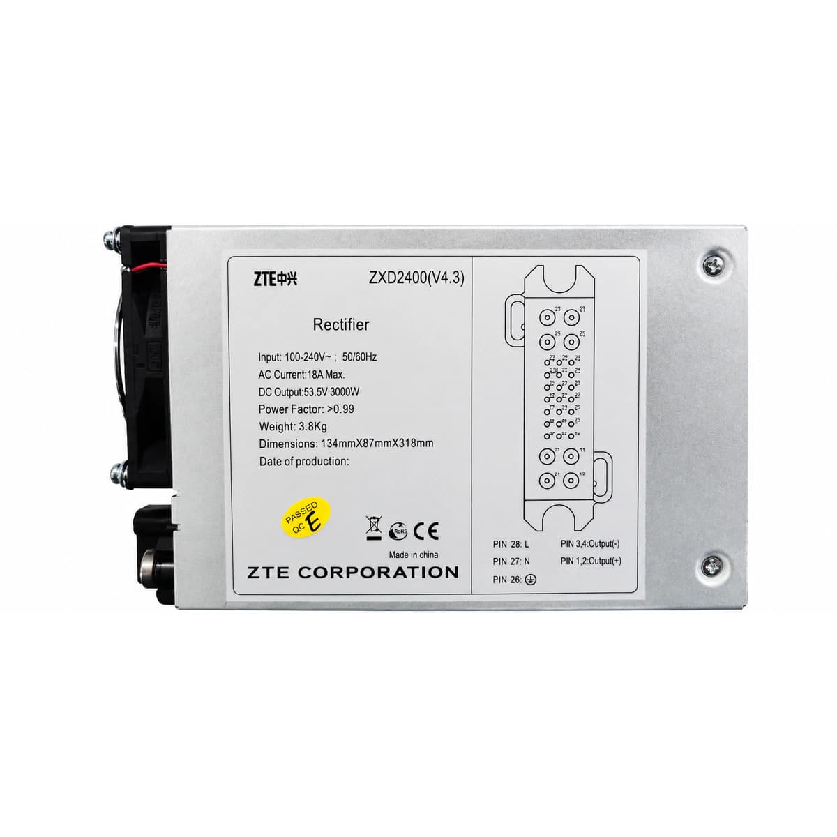
1. Industry Context and ZXD2400 Electrical Architecture
Across telecom base stations, railway signaling networks, and central offices, the ZTE ZXD2400 series (including revisions V4.0, V4.1, V4.2, and V4.3) stands as one of the most widely deployed high-frequency switch-mode rectifiers globally. Engineered with single-ended active power factor correction (APFC) and a robust PWM full-bridge conversion topology, it delivers an output of -48VDC / 50A (2400W nominal) under standard 220VAC single-phase grids, and automatically derates to 48VDC / 30A (1440W) under 110VAC/120VAC environments.
During emergency site repairs, off-grid battery bank reactivation, or equipment bench testing, field engineers frequently lack a full ZXDU68 or ZXDU58 subrack chassis and central supervision unit (CSU). Mastering the rear pinout definitions and executing reliable standalone startup is an indispensable operational skill.
Rated AC Input Range:
220VAC nominal, operating across 80VAC to 300VAC wide-range inputDC Output Specifications:
-48VDC nominal, adjustable float range 42VDC to 58VDCEfficiency & Power Factor:
Nominal efficiency ≥90%, power factor ≥0.99
2. Rear Connector Pinout Topology and Signal Mapping
The ZXD2400 utilizes an integrated blind-mate multi-pin rear connector housing AC utility inputs, high-current DC bus terminals, and low-voltage monitoring signals. Facing the rear connector, pins are structured into distinct functional zones:
L / N / PE (High-Voltage AC Terminals): Connects single-phase 220VAC live, neutral, and protective earth. The PE contact is physically elongated for safety-first ground contact during hot plugging.
+48V / -48V (DC Power Bus Output): Heavy-duty copper busbar terminals capable of delivering 50A continuous DC current.
ON/OFF (Inhibit / Startup Logic): Active-low enable control pin. Left floating, the module remains inhibited or in standby mode.
GND_S / SENSE+ / SENSE- (Remote Voltage Sense): Detects real-time battery terminal drop and dynamically compensates for distribution line losses.
CAN_H / CAN_L / RS485 (Digital Supervision Bus): Differential communication bus interfacing with central controllers for telemetry, telecommand, and status reporting.
SHARE (Active Current Share Pin): Analog interconnect line enabling multi-module parallel load sharing with current imbalance below ±3%.
3. Step-by-Step Standalone Startup Wiring (Without Controller)
To operate the rectifier independently without a backplane supervisory controller, a closed startup loop must be established. Ensure power is completely disconnected before proceeding with the following sequence:
Step 1 (De-energize and Verify): Open upstream AC circuit breakers. Use a calibrated multimeter to confirm zero residual voltage across all AC and DC terminal pins.
Step 2 (Enable Signal Jumper): Locate the ON/OFF enable pin and the signal ground (GND_S) pin on the auxiliary connector. Securely bridge them using an insulated 0.5 mm² wire jumper to ground the enable line.
Step 3 (AC Utility Connection): Connect dedicated 220VAC power cabling firmly to L, N, and PE terminals. Close the AC breaker.
Step 4 (Soft-Start and Voltage Verification): Observe the green front panel LED. Following a 3-second soft-start delay, the internal cooling fan executes a speed diagnostic, and the module ramps smoothly to default 53.5VDC.
4. Output DC Voltage Fine-Tuning and Protection Thresholds
When running off-line without digital commands from a system controller, output voltage is governed by internal trimmer potentiometers (W1/W2):
Factory Default Float Setting: Calibrated at 53.5VDC out of the box, optimized for standard 48V VRLA battery string float maintenance.
Equalize & Boost Charging Adjustment: Clockwise rotation adjusts voltage upwards to 56.4VDC for equalizing cycles; counter-clockwise lowers voltage down to 45VDC~48VDC for bench testing.
Over-Voltage Protection (OVP Threshold): Hard-coded hardware protection trips if output reaches 59.0VDC ±0.5V, causing immediate latch-off. AC mains must be cycled off until internal bulk capacitors discharge.
5. Tri-Color Status LED Diagnostics and Field Troubleshooting
The front bezel features three primary diagnostic LEDs indicating operating conditions and internal power-stage status:
Green LED (RUN): Solid illumination indicates normal operation and regulated DC output. Extinguished indicates absence of AC mains or internal auxiliary power failure.
Yellow LED (ALM - Warning): Illuminates during non-critical faults such as AC under-voltage (<80VAC), AC over-voltage (>300VAC), or thermal limiting. Automatically resets upon condition clearance.
Red LED (FAULT): Solid illumination signals critical lockout, including DC over-voltage latch, fan stall, or shorted power switching devices. Requires off-line service.
6. Engineering Technical Support and Spare Parts Procurement
For certified ZTE ZXD2400 modules, drop-in replacement options, or complete -48V DC power subracks, contact RICEWIND engineering support:
Official Email: lee@ricewind.com | Engineering Direct: +86 17621197907
Engineering Procurement & Technical Desk
For technical datasheets, custom power topology design, or volume export quotations, reach out to HEFENGQI engineers.