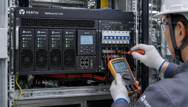
1. NetSure 531 A41 Subrack Architecture and Power Topology
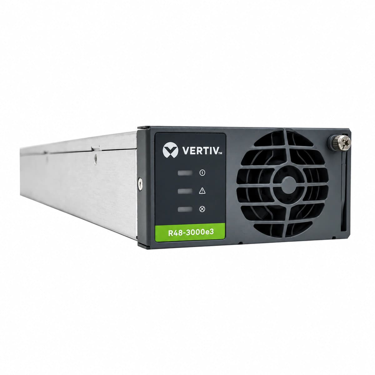
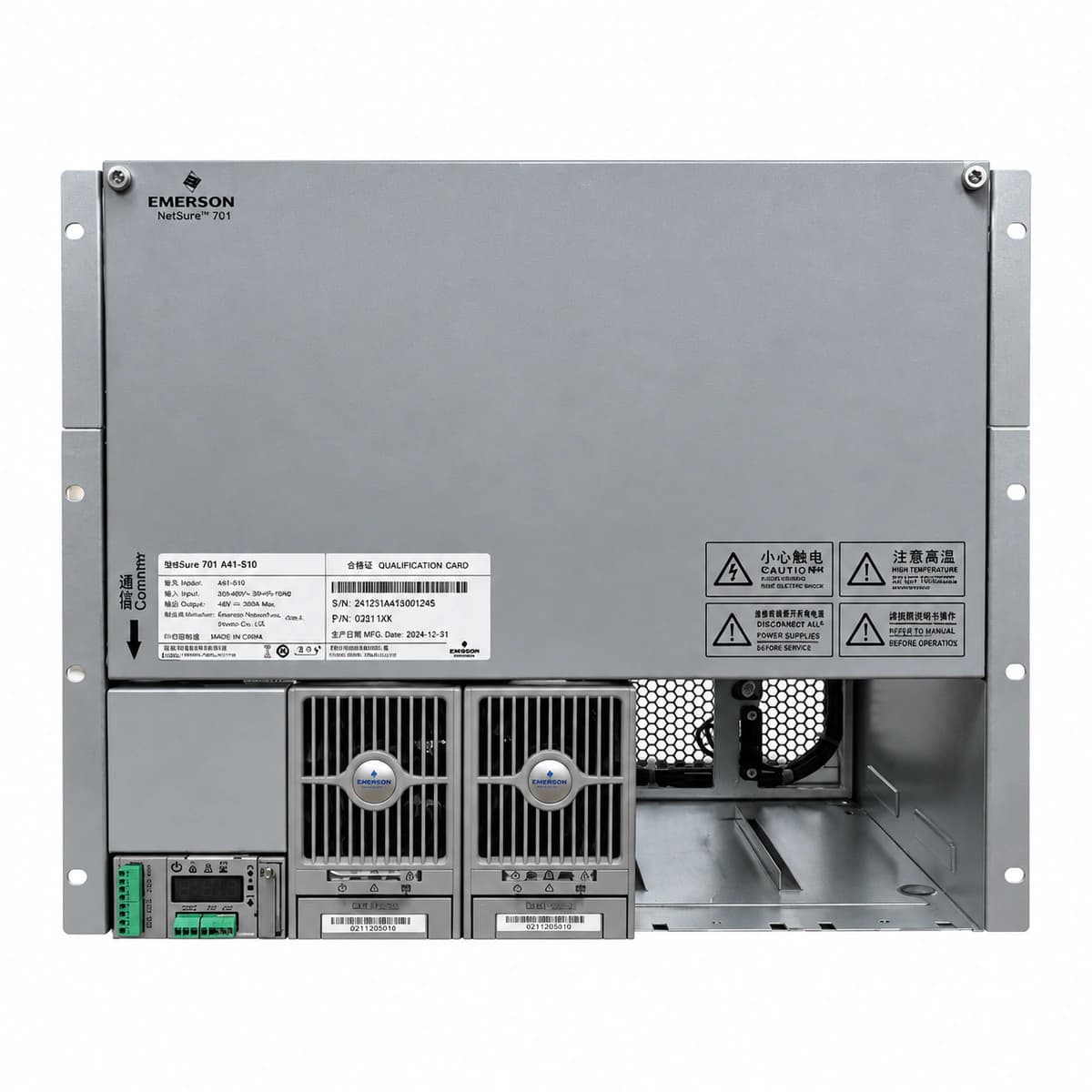
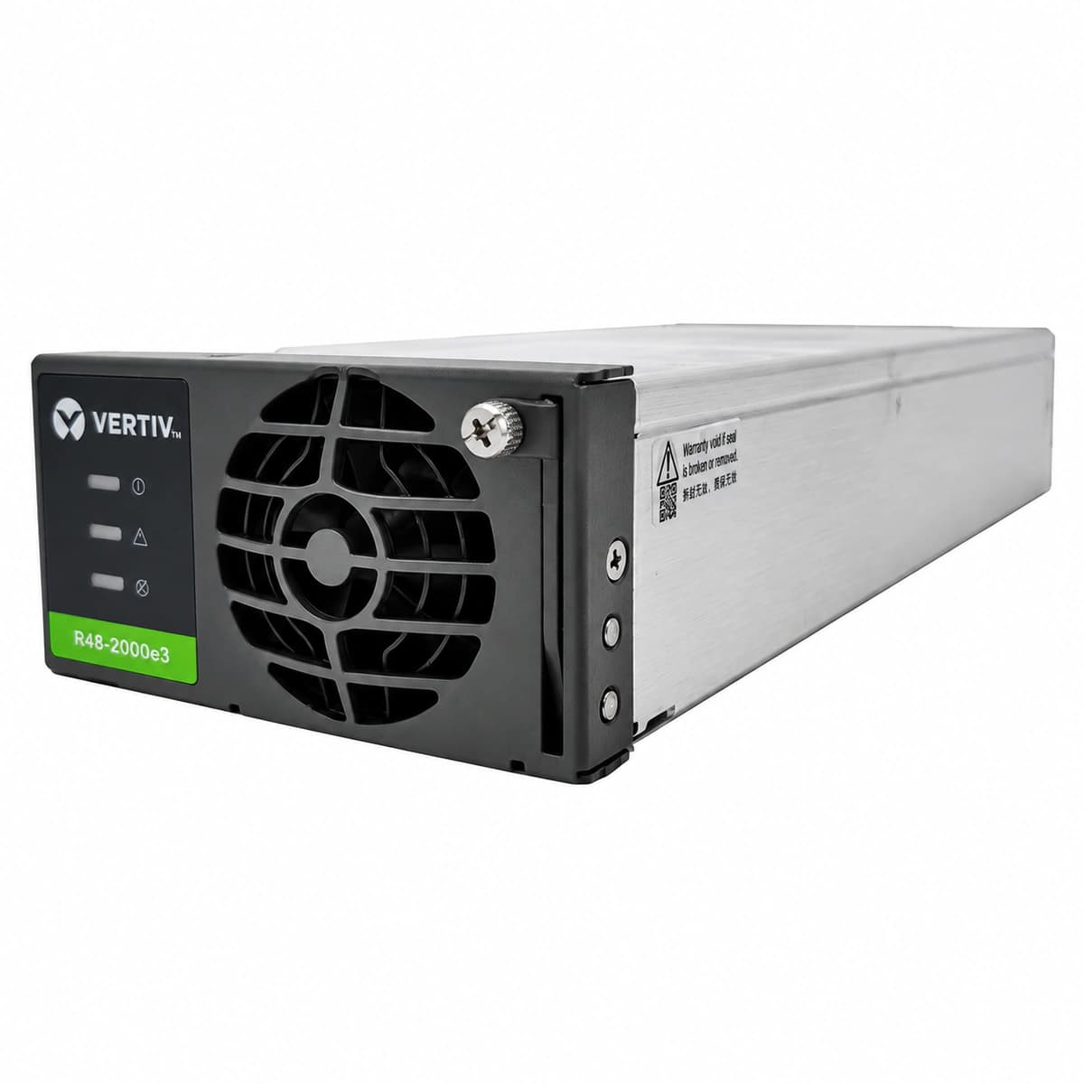
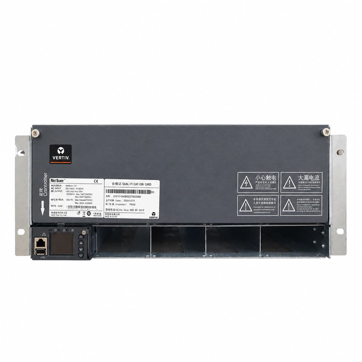
In 5G macro base stations, optical transmission nodes, and enterprise datacenter shelters, the NetSure 531 A41 embedded power system developed by Vertiv (formerly Emerson Network Power) is globally recognized for rock-solid DC power conversion. Operating in a standard 19-inch rack form factor with a 4U footprint (483mm W x 310mm D x 177mm H), the system accommodates up to four Vertiv eSure R48 series rectifier modules (such as the R48-2000e3 or R48-3000e3), delivering an aggregate output from 120A to 200A at a nominal -48Vdc.
The chassis features a full front-access functional layout: the left side houses four hot-swappable rectifier bays and one central controller slot (M830B or M221S/M222S); the right side integrates AC mains input circuit breakers, battery management branches, dual-stage LLVD/BLVD load distribution bars, and Class C surge protective devices (SPD).
2. AC Mains Input and Grounding System Engineering Practices
Safe installation begins with rigorous adherence to AC utility wiring and electrical grounding standards. NetSure 531 A41 accommodates single-phase three-wire (220Vac) or three-phase five-wire (380Vac) configurations:
Mandatory wiring rules include:
Protective Earth (PE) Grounding: Dedicated M6 copper grounding bolts are located on the rear and lower-right front panel. Use multi-strand yellow-green copper ground cable (minimum 16mm²) connected to the station ground bar. Measured ground resistance must remain ≤5Ω (or ≤1Ω at high-lightning tower sites);
AC Input Termination: In single-phase systems, terminate Phase to L and Neutral to N. Install a 63A/2P upstream breaker. Torque all terminal screws to 2.5N·m–3.0N·m to prevent contact degradation under sustained thermal cycling;
Surge Protection Verification: Confirm the mechanical inspection window on the SPD cartridge displays solid green. If the window turns red, the internal varistor is compromised and must be replaced immediately prior to main breaker engagement.
3. Battery Bank Cabling and Two-Stage Low Voltage Disconnect (LLVD/BLVD)
The NetSure 531 A41 integrates two internal magnetic-latching contactors that govern Load Low Voltage Disconnect (LLVD) for shedding secondary circuits, and Battery Low Voltage Disconnect (BLVD) to prevent destructive deep battery discharge:
Common Positive Ground Busbar (+0V): The positive bus serves as the common zero-potential reference for the -48V system and must be solidly bonded to the equipment room master ground bar;
Battery Feeders: Terminate dual battery banks to dedicated hydraulic MCBs (typically 2x 63A/1P or 100A/1P). Utilize flame-retardant copper conductors (25mm²–35mm²). Attach the external NTC temperature sensor probe to the battery casing and plug the harness into the controller TEMP port for dynamic float compensation;
LLVD Load Distribution: Connect non-critical equipment (climate controllers, auxiliary lighting, surveillance) to the LLVD busbar (typically 2x 32A and 2x 16A MCBs). These circuits are automatically shed during initial battery rundown;
BLVD Load Distribution: Connect mission-critical telecommunications gear (5G BBUs, optical multiplexers, core switches) to the BLVD busbar, ensuring uninterrupted power until the battery bank approaches its ultimate cutoff limit.
4. M830B / M221S Controller Parameter Configuration
After mechanical cabling is certified, energize the system and navigate the M830B controller LCD interface (or access the embedded web console via 192.168.0.10) to program system settings:
Float and Equalize Voltage Setpoints: For standard VRLA lead-acid batteries, configure Float Voltage to -53.5Vdc (2.23V/cell) and Equalize Voltage to -56.4Vdc (2.35V/cell). For telecom lithium iron phosphate (LiFePO4) batteries, switch to constant voltage charge mode (-54.0Vdc) or enable automated CAN/RS485 BMS telemetry;
Charge Current Limit: Restrict maximum recharge current to 0.1C–0.15C of total battery capacity (e.g., 20A–30A for a 200Ah battery string);
LLVD Threshold Voltage: Set between -45.0Vdc and -46.0Vdc with a 10–30 second debounce timer to shed non-essential loads during early grid outages;
BLVD Threshold Voltage: Set to -43.2Vdc (1.80V/cell cutoff). When battery voltage declines to this floor, the contactor opens completely, eliminating the risk of permanent cell reversal or sulfation.
5. On-Site System Energization, Commissioning, and Fault Troubleshooting
Execute the initial live commissioning sequence following this systematic checklist to eliminate inrush surges and busbar instability:
Open All Circuit Breakers: Ensure all load and battery breakers are initially open. Close only the AC utility feeder; observe the M830B controller boot with a green LED and no audible alarm;
Sequential Rectifier Insertion: Slide Vertiv eSure R48 rectifiers into slots one by one, latching the front ejector handles. The internal fans spin up for self-check, the green Run LEDs lock solid, and the controller displays the registered rectifier count while bus voltage smoothly stabilizes at -53.5Vdc;
Measure Polarity and Bus Potential: Use a calibrated digital multimeter at the open battery breaker terminals to verify voltage (-53.3Vdc to -53.7Vdc) and confirm correct polarity before closing battery circuits;
Engage Battery and Verify Charge Current: Close the battery MCBs and monitor controller readings to ensure normal low-current float charging;
Progressive Load Activation: Close load circuit breakers one by one. If a Contactor Open or DC Undervoltage alarm occurs, navigate to the controller manual test menu to cycle the contactor; if Rectifier Imbalance appears, verify connector seating on the backplane.
6. Direct Factory Supply and Global Telecom Support
RICEWIND (Hangzhou Hefengqi Communication Technology Co., Ltd.) is a specialized manufacturer and global turnkey supply platform for telecom-grade DC power systems, modular high-efficiency rectifiers, precision climate cabinets, and power distribution units. We maintain immediate inventory for the entire Vertiv NetSure portfolio (NetSure 531 A41, NetSure 731 A41, NetSure 7100), eSure R48 rectifiers, M830B controllers, and distribution accessories.
For comprehensive NetSure electrical schematics, CAD dimensions, BMS lithium battery integration guides, or project supply inquiries, contact our engineering support team: Email: lee@ricewind.com | Mobile / WhatsApp: +86 17621197907
Engineering Procurement & Technical Desk
For technical datasheets, custom power topology design, or volume export quotations, reach out to HEFENGQI engineers.