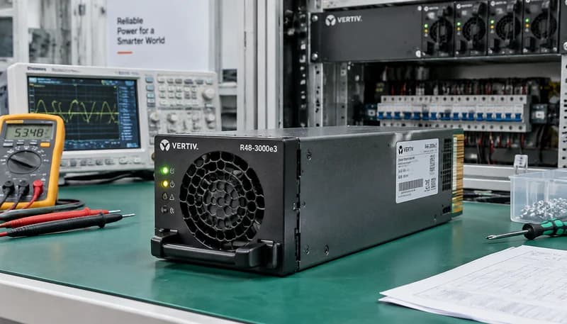
1. Vertiv eSure R48 Rectifier Series Architecture and Electrical Specifications
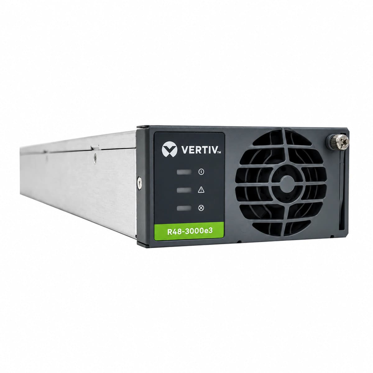
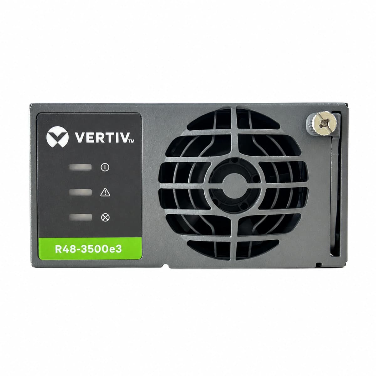
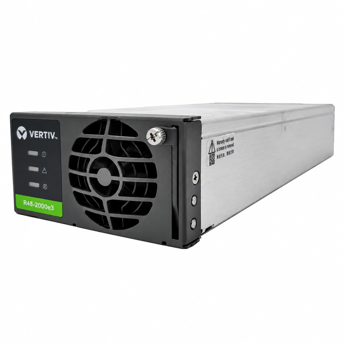
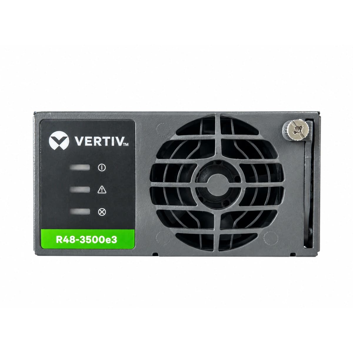
Within modern telecom base stations and mission-critical datacenter DC power plants (such as NetSure 731, NetSure 531, and NetSure 7100 subrack systems), the eSure series of high-frequency switchmode rectifier modules manufactured by Vertiv (formerly Emerson Network Power) serves as the primary AC-to-DC power conversion workhorse. Leading industrial models include the R48-2000e3 (30A/2000W), R48-3000e3 (50A/3000W), and the heavy-duty R48-3500e3 (60A/3500W).
Engineered with fully digital DSP control and Active Power Factor Correction (APFC), this series delivers a power factor ≥0.99 and peak conversion efficiency between 95.5% and 96.5%. The nominal input voltage window spans 200Vac to 250Vac with extreme grid tolerance from 85Vac to 300Vac. The nominal DC output is -48Vdc, continuously adjustable from -42Vdc to -58Vdc. Supporting true live hot-plugging and constant-power output, the module delivers 100% full-rated capacity from -40°C to +45°C ambient, transitioning into linear thermal derating between +45°C and +75°C.
2. Backplane Connector Gold-Finger Pinout and Signal Architecture
The Vertiv eSure R48 rectifier features an integrated rear blind-mate edge connector designed for toolless insertion into the NetSure subrack backplane. This interface is partitioned into AC input power blades, DC output power terminals, and a multi-pin low-voltage signal block (J1 connector). Mastering exact pin designations is paramount for off-grid bench testing, emergency standalone commissioning, and third-party PLC integration.
Primary pin assignments and functional parameters include:
AC Input Blades: L (Phase), N (Neutral), PE (Protective Earth with an extended contact pin to ensure grounding precedence during insertion and extraction);
DC Output Terminals: OUTPUT+ (Positive reference bus), OUTPUT- (Negative -48Vdc primary busbar interface);
CAN Bus Communication Pins: CAN_H and CAN_L differential lines operating at a standard 125 kbps baud rate for bidirectional telemetry with M221S, M222S, and M830B controllers;
Power Enable and Slot Addressing: SLOT_ID (automatic hardware address coding pin), REMOTE_ON / PWR_EN (power enable pin pulled down to signal ground to activate main power rail conversion);
Hardware High Voltage Shutdown (HVSD): Overvoltage feedback bus facilitating latching trip or dual-event auto-restart protocols.
3. Standalone Startup and Bench Testing Wiring Procedures
When operating an R48 module outside a NetSure subrack (such as during workshop repairs, off-grid testing, or repurposing as a high-amperage bench power supply), the unit defaults into autonomous fallback mode (stabilized at 53.5Vdc float voltage). However, without proper enable grounding, the DSP may hold the main power train in soft standby. Technicians must execute the following verified startup sequence:
Safety and Terminal Insulation: Verify the AC feeder breaker is open; connect the PE terminal to solid earth ground; connect a calibrated DC electronic load or high-wattage power resistor to the output terminals;
Enable Jumper Placement: Locate the REMOTE_ON / PWR_EN pin and the low-voltage signal reference pin (GND); bridge these pins utilizing a 1kΩ to 4.7kΩ metal-film resistor or short jumper wire to pull the enable circuit low;
Power Initialization and Validation: Engage the AC mains supply. Observe the front cooling fan accelerate to full speed during an initial 3-second diagnostic spin. The green Run LED will flash briefly before locking into solid illumination, while the yellow and red LEDs remain dark. The DC bus smoothly ramps to 53.5Vdc within 5 seconds.
4. CAN Bus Digital Voltage Tuning and Autonomous Current Sharing
Vertiv eSure R48 modules interact with supervisory controllers via the CAN 2.0B protocol at a fixed 125 kbps rate. By broadcasting structured command frames from an external MCU (e.g., STM32, ESP32, or industrial gateway), engineers can dynamically modulate output voltage between -42Vdc and -58Vdc and adjust current limits between 10% and 120%.
Key communication attributes and control mechanics:
Telemetry Broadcast: The module continuously broadcasts real-time operating metrics every 1000ms, encompassing AC mains voltage, DC bus voltage, output load current, heatsink temperature, fan duty cycle, and internal alarm bitmasks;
Command Frame Injection: The external controller injects target voltage and current-limit setpoints every 500ms to 1000ms. If CAN heartbeats cease for more than 30 seconds, the internal watchdog automatically shifts the module back into its safe 53.5Vdc default float voltage;
Active Current Sharing: In multi-module parallel operation (up to 30 units on a common DC bus), the internal DSP current-sharing algorithm maintains inter-module current divergence within a tight ±1.5A tolerance across 10% to 100% load.
5. Diagnostic Resolution of Five Critical Field Alarm Codes
Front-panel tricolor LED indicators (Green: Run, Yellow: Protection, Red: Fault) provide immediate diagnostic visibility into underlying hardware and grid anomalies. Below are field-tested recovery protocols for the five most frequent site alarms:
Green LED Off, Yellow LED Solid (AC Input Out of Range): The grid voltage is below 80Vac or above 305Vac, or the AC input phase breaker has tripped. Inspect input terminal torque and grid quality; the module automatically resumes operation once grid voltage returns between 85Vac and 300Vac;
Yellow LED Flashing (Communication Failure): CAN link lost. Verify that the module is firmly locked in its subrack slot; inspect the 120Ω terminating resistors on the M221S/M830B bus; check the backplane connector for oxidation or pin deflection;
Red LED Solid (High Voltage Shutdown / HVSD): Output overvoltage lockout triggered when the DC rail surpasses 59.5Vdc~60Vdc. If latched under dual-trip protocol, disengage the module from the subrack for 10 seconds to fully discharge internal primary caps before reseating. Persistent red illumination indicates internal secondary MOSFET breakdown requiring hardware replacement;
Red LED Flashing (Rectifier Fan Failure): Cooling fan seized or tachometer signal lost. Check the front intake grill for dust accumulation or foreign debris; rotate the fan blades with an insulated tool to detect bearing seizure. If the fault persists, remove the front bezel screws and replace the modular hot-swap fan assembly in the field;
Yellow LED Solid with Output Throttling (Thermal Derating): Heatsink temperature has exceeded +45°C. Clean intake air filters, inspect cabinet extraction airflow, and ensure at least 800mm of clearance behind the subrack exhaust.
6. Technical Engineering Support and Direct Factory Supply
RICEWIND (Hangzhou Hefengqi Communication Technology Co., Ltd.) is a specialized manufacturer and global supply chain provider of telecom-grade DC power systems, modular high-efficiency rectifiers, precision climate-controlled enclosures, and intelligent distribution units. We maintain immediate inventory and provide complete engineering support for the entire Vertiv eSure portfolio (R48-3000e3, R48-3500e3, R48-2000e3), NetSure controllers, and subracks.
For technical datasheets, CAD dimensional drawings, CAN protocol development kits, or volume project procurement, contact our international technical response team: Email: lee@ricewind.com | Mobile / WhatsApp: +86 17621197907
Engineering Procurement & Technical Desk
For technical datasheets, custom power topology design, or volume export quotations, reach out to HEFENGQI engineers.