PCE vs. PUE: Resolving the Upstream Capacity Allocation Paradox
For more than two decades, the data center industry has relied on Power Usage Effectiveness (PUE) as the primary benchmark for facility energy performance. While PUE succeeds in characterizing operational energy efficiency after commissioning—expressed as the ratio of total facility energy to IT equipment energy over an annualized period—it possesses fundamental thermodynamic and architectural blind spots. Crucially, PUE is an operational metric that completely obscures structural electrical capacity allocation during initial design and facility master planning. It does not account for boundary inconsistencies regarding fan power integration inside liquid-cooled server chassis, floating parasitic loads, variable IT utilization across training checkpoints, or shared utility metering in complex multi-tenant campuses. More critically, an operator can boast a deceptively low operational PUE of 1.15 while leaving tens of megawatts of upstream utility capacity structurally stranded in over-provisioned, idle auxiliary infrastructure.
To resolve this structural disconnect in an era marked by rigid utility grid connection caps and 24 to 48 month substation transformer interconnection delays, the Open Compute Project (OCP) framework establishes Power Compute Effectiveness (PCE). Mathematically defined as the ratio of provisioned IT compute power to total provisioned facility capacity (PCE = P_IT_provisioned / P_facility_provisioned), PCE evaluates the design efficiency of upstream capital and electrical capacity allocation. Unlike PUE, which monitors operational kilowatt-hours consumed at the meter, PCE isolates precisely where nameplate electrical headroom is permanently locked into legacy mechanical chillers, redundant double-conversion uninterrupted power supply (UPS) conversion stages, power distribution unit (PDU) transformation losses, and static facility overhead prior to compute energization. Optimizing PCE directly addresses the acute stranded power crisis, transforming non-compute capital allocation into deployable silicon capacity within hard utility caps.
Establish design-phase PCE baseline: Calculate nameplate IT capacity against gross utility interconnect capacity prior to equipment procurement.
Delineate parasitic fan power and auxiliary pumping boundaries strictly according to OCP Data Center Facility workgroup standards.
Map utility interconnection contractual limits against cumulative internal transformation deratings to expose stranded upstream kilovolt-amperes.
Deconstructing Non-Compute Overhead & Quantifying Stranded Megawatts
In a conventional 100 MW facility design built around air-cooled server topologies and traditional alternating current (AC) electrical distribution, non-compute infrastructure consumes between 30% and 50% of total provisioned electrical capacity. A granular breakdown of non-compute allocation reveals massive capacity sinks: mechanical vapor-compression chillers, condensation pumps, and cooling tower assemblies absorb 15 to 25 MW of provisioned capacity to satisfy extreme summer wet-bulb design conditions; electrical conversion systems—encompassing medium-voltage (MV) to low-voltage (LV) step-down transformers, central double-conversion static UPS systems, and localized PDU transformers—sequester 7 to 10 MW; and general building services, fire suppression systems, and office auxiliary loads occupy approximately 3 MW. Consequently, legacy air-cooled enterprise data centers routinely operate at a PCE of only 0.50 to 0.65, meaning that for every 100 MW allocated from the utility substation, only 50 to 65 MW ever energizes compute silicon.
Modern colocation facilities optimize these systems marginally to achieve a PCE of 0.70 to 0.75, yet significant structural headroom remains locked behind conservative engineering margins. State-of-the-art architectures deploying dense direct-to-chip liquid cooling (DLC) and streamlined power pathways routinely achieve PCE ratings between 0.82 and 0.88. The macroeconomic impact of this upstream reallocation within a fixed grid envelope is profound: transitioning a 100 MW substation-limited campus from a legacy PCE baseline of 0.70 (70 MW compute, 30 MW non-compute overhead) to an advanced PCE of 0.85 (85 MW compute, 15 MW overhead) systematically liberates 15 MW of pure compute capacity. Within modern high-density hardware topologies, this recovered 15 MW can fully power a cluster of over 15,000 top-tier AI training GPUs without submitting a single interconnection request to the regional utility.
Execute facility-wide infrastructure capacity audits to decompose provisioned non-compute allocation across chillers, UPS, and auxiliary gear.
Calculate site-specific PCE sensitivity metrics to quantify the financial and compute yields of converting 1 MW of parasitic headroom into active IT capacity.
Establish strict engineering rules disallowing static N+1 mechanical redundancy sizing that artificially penalizes IT provisioned limits.
Thermodynamic Optimization: Chiller Elimination & Direct-to-Chip Liquid Cooling
The thermodynamic mechanism most responsible for depressing facility PCE is the reliance on centralized mechanical vapor-compression chillers. Sizing a chilled-water plant for peak ambient dry-bulb and wet-bulb excursions imposes a structural PCE penalty of 0.18 to 0.25 on the total facility envelope. Centrifugal chillers operating with sub-10°C evaporator supply temperatures require massive electrical provisioning to drive large compressor motors, locking up nameplate power that cannot be reassigned to IT racks during off-peak thermal periods. To eliminate this electrical deadweight, infrastructure architects must transition from chilled-water refrigeration loops to warm-water direct-to-chip liquid cooling (DLC) architectures utilizing closed-circuit variable-speed adiabatic dry coolers or cooling towers operating strictly in sensible economization modes.
By adhering to ASHRAE W3 and W4 liquid cooling guidelines, which permit secondary supply water temperatures between 32°C and 45°C directly to cold plates, facilities can achieve 100% dry-cooler economization year-round across virtually all global climate zones. Cold plates featuring micro-channel geometries achieve thermal resistances below 0.015 K/W, permitting direct extraction of over 85% of total server heat without phase-change refrigeration. Consider a 50 MW total provisioned facility: a traditional chilled-water design demands up to 10 MW of dedicated cooling power capacity, yielding a PCE of approximately 0.74. Transitioning that same site to an optimized ASHRAE W4 DLC loop equipped with electronically commutated (EC) dry cooler fans and high-efficiency variable-frequency drive (VFD) circulation pumps drops required cooling provisioning to roughly 5 MW. The resulting PCE shifts to 0.84, immediately reallocating 5 MW of pure electrical capacity to compute clusters on paper before breaking ground on civil construction.
Specify ASHRAE W3/W4 compliant secondary fluid networks with inlet facility water temperatures engineered between 32°C and 45°C.
Eliminate compressor-based vapor-compression refrigeration circuits, replacing them with variable-speed adiabatic dry coolers.
Deploy dual-gradient micro-channel cold plates capable of capturing >=85% of server thermal dissipation directly into the liquid circuit.
Electrical Conversion Efficiency: Telecom-Grade DC Distribution & SiC Rectification
Beyond thermodynamic modifications, reclaiming stranded megawatts requires confronting electrical transformation topologies. Traditional alternating current (AC) distribution pathways introduce substantial cascading conversion losses: medium-voltage grid power is stepped down to 480V/415V AC, passed through central double-conversion static UPS systems (AC to DC to AC), distributed via copper busways to floor power distribution units (PDUs) featuring internal isolation transformers, and finally routed to individual server switch-mode power supplies (PSUs) where it is rectified to DC and stepped down to 12V or 48V. This multi-tiered conversion cascade imposes an 8% to 12% fixed thermal overhead that not only consumes raw electrical capacity but also necessitates secondary parasitic cooling loads to evacuate heat from electrical rooms.
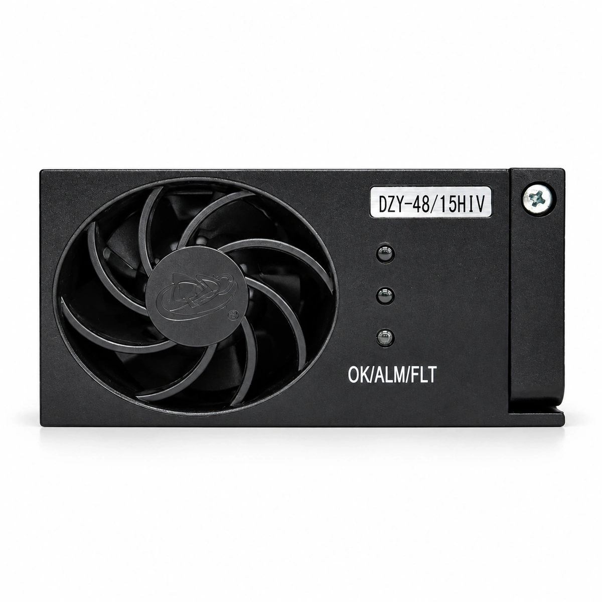
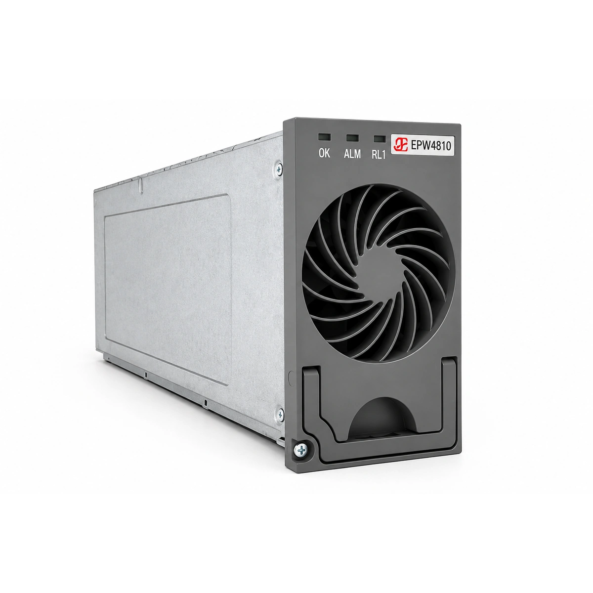
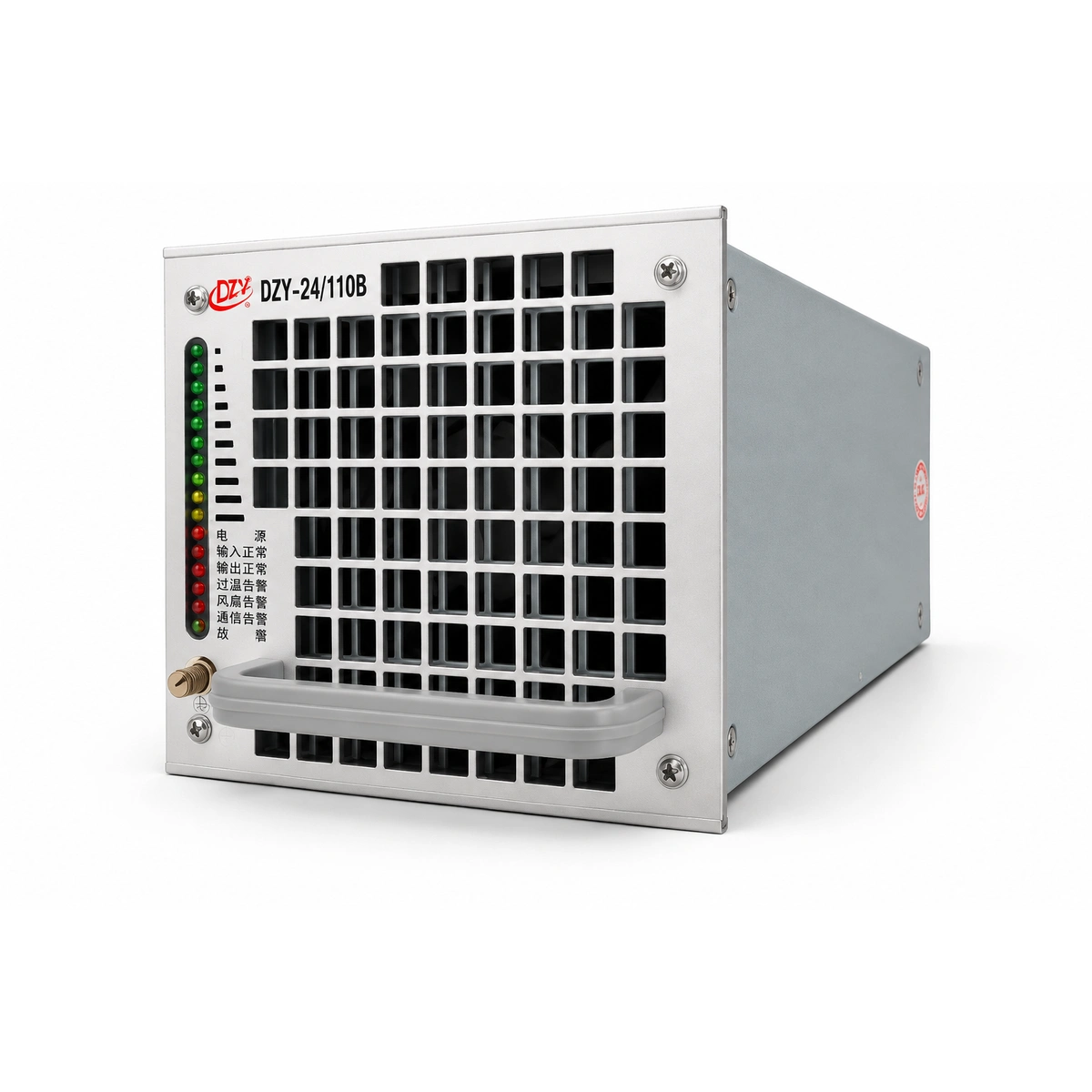
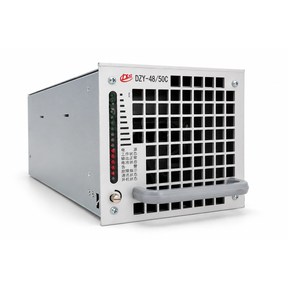
To maximize PCE, modern high-density facilities must eliminate transformation tiers by deploying direct medium-voltage rectification and high-voltage direct current (HVDC) topologies. Implementing direct 415V AC to 380V DC or telecom-grade -48V/380V busway architectures removes redundant inversion stages, feeding power straight to server power entry points. Utilizing next-generation silicon carbide (SiC) wide-bandgap semiconductor devices within modular rectifiers drives electrical conversion efficiencies above 97.5%, while distributed rack-level battery energy storage systems (BESS) replace centralized lead-acid or lithium UPS plants. By distributing battery backup directly inside the compute lineup and eliminating intermediate isolation transformers, upstream electrical losses drop by more than 60%. This streamlines the electrical distribution overhead and directly expands the available IT capacity budget within the constrained utility envelope.
Implement 380V HVDC or 415V direct-rectified busway distribution to bypass redundant AC-to-DC-to-AC conversion stages.
Specify silicon carbide (SiC) semiconductor topology in all central and rack-level rectifiers to ensure conversion efficiencies exceed 97.5%.
Integrate distributed rack-level BESS architecture to eliminate central UPS footprints and eliminate transformation loss cascades.
Brownfield AI Retrofit Protocol: Extracting IT Headroom under Grid Caps
While greenfield hyperscale developments can integrate high-PCE principles from inception, the immediate industrial challenge lies in brownfield legacy facilities stranded beneath fixed electrical utility agreements. Confronting 24 to 48 month lead times for regional transmission upgrades and substation transformer allocations, operators cannot simply request additional utility capacity to accommodate modern AI densities. Infrastructure architects must employ a standardized brownfield audit protocol utilizing PCE sensitivity matrices to systematically identify and harvest stranded power locked within aging data halls. These audits systematically trace parasitic power footprints across obsolete computer room air handling (CRAH) units, legacy static transfer switches, under-utilized raised-floor air plenums, and low-efficiency centralized transformer lineups.
A representative case study illustrates the brownfield potential: a 40 MW legacy enterprise campus was operating at a PCE of 0.65, supporting 26 MW of legacy compute while consuming 14 MW in non-compute infrastructure. By executing an aggressive brownfield retrofit program—stripping out obsolete perimeter DX CRAC units, installing high-density in-row coolant distribution units (CDUs) connected to external dry-coolers, and replacing centralized SCR-based UPS systems with modular SiC-based DC rectification bays—the site's PCE was elevated to 0.82. This internal thermodynamic and electrical restructuring reduced non-compute overhead from 14 MW down to 7.2 MW. The resulting 6.8 MW of newly liberated IT headroom was directly reallocated to high-density accelerated compute hardware, completely circumventing multi-year utility queue delays and unlocking over 65 million dollars in annualized compute value without extending the building footprint.
Conduct comprehensive brownfield PCE sensitivity audits to identify low-efficiency perimeter DX CRAC/CRAH systems for immediate decommissioning.
Deploy modular in-row liquid CDUs with variable-speed primary pumps to replace broad-area legacy air-cooling systems.
Replace central double-conversion UPS infrastructure with high-efficiency distributed SiC rectifiers to instantly capture stranded transformation kilowatts.
OCP Standardization, CapEx-to-Capacity Modeling & Supervisory Governance
To achieve industry-wide scalability, PCE principles must be formalized within open hardware governance bodies. The Open Compute Project (OCP) Data Center Facility (DCF) workgroup has initiated efforts to standardize PCE boundary definitions, creating strict measurement criteria that prevent greenwashing through arbitrary sub-metering exclusions. This standardized framework enables capital committees to execute rigorous CapEx-to-Capacity modeling. When evaluating the capital expenditure required to install liquid cooling distribution manifolds, SiC rectifiers, and dry-cooler circuits, financial models must weigh these upfront investments against the catastrophic opportunity cost of stranded revenue and stalled AI product launches caused by utility grid delays. The cost of a 15 MW liquid-and-DC retrofit is routinely amortized within 6 to 9 months when measured against the immediate revenue generated by deploying modern AI compute.
Sustaining target PCE levels across dynamic AI operational lifecycles demands real-time supervisory governance integrated within the Data Center Infrastructure Management (DCIM) and facility SCADA planes. High-performance AI workloads induce severe electrical transients, swinging from idle states to extreme load spikes in milliseconds during training model initializations. Infrastructure governance platforms must utilize high-speed branch circuit telemetry, thermal predictive modeling, and automated variable-frequency controls across fluid pumps and dry-cooler fan arrays. By continuously matching mechanical and electrical operation to real-time silicon demand curves rather than fixed peak-capacity buffers, modern facilities maintain design PCE targets greater than 0.85 across volatile, dynamic compute profiles over their entire operating lifespans.
Incorporate OCP DCF-standardized PCE verification boundaries into all future facility engineering procurement specifications.
Adopt CapEx-to-Capacity financial modeling that balances liquid conversion investments directly against utility grid queue delay costs.
Deploy sub-millisecond branch circuit telemetry and automated supervisory SCADA controls to dynamically maintain PCE targets across AI load spikes.
Engineering Procurement & Technical Desk
For technical datasheets, custom power topology design, or volume export quotations, reach out to RICEWIND engineers.