The High-Density Liquid Cooling Dilemma: Tolerance Stack-Up and Hot-Aisle Service Bottlenecks
The rapid escalation of thermal design power (TDP) in artificial intelligence compute nodes—driven by highly parallel multi-accelerator architectures such as NVIDIA Blackwell B200 and Ultra platforms—has made direct-to-chip liquid cooling an absolute physical requirement. High-density compute racks operating at 120kW to 160kW demand high volumetric flow rates, typically ranging from 1.5 to 3.0 liters per minute (LPM) per accelerator cold plate, yielding cumulative rack-level flow rates between 60 and 100+ LPM. To maintain operational safety and hyperscale deployment velocity, all maintenance operations must occur strictly within the front cold aisle. Technicians cannot access the rear hot aisle, where extreme exhaust thermal plumes, dense ±400V or 48V DC busway architectures, and high-pressure fluid distribution manifolds present acute physical and electrical hazards.
In dense multi-sled architectures spanning standard 44U to 48U rack envelopes, strict front-aisle servicing introduces an unforgiving mechanical tolerance challenge. Cumulative structural tolerance stack-ups—incorporating sheet metal fabrication variances, drawer slide deflection, thermal chassis expansion, and stainless steel manifold weld positioning errors—routinely reach ±1.5mm to ±3.0mm in lateral and vertical planes. When standard rigid blind-mate quick disconnects (QDs) engage under these misalignments, the resulting side-loading creates high friction, galling of metallic guidance pins, connector jamming, and uneven elastomeric compression. These mechanical stresses dramatically increase insertion force requirements, risk severe frame deformation during hot-swapping, and frequently precipitate micro-leaks capable of disabling mission-critical compute infrastructure.
Quantify total worst-case chassis, manifold, and rail tolerance stack-up across the full operational thermal gradient (0°C to 85°C).
Enforce cold-aisle-only service access policies, eliminating manual rear hot-aisle interventions around energized busbars.
Establish an insertion force threshold of <150 N per sled connection pair to guarantee safe ergonomic manual installation.
Kinematics of Pivoting Blind-Mate Couplings (PBMC): Radial Articulation and Angular Self-Alignment
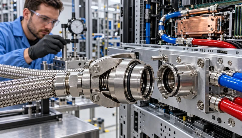
Pivoting Blind-Mate Coupling (PBMC) technology, codified through Open Compute Project (OCP) liquid cooling subcommittees, resolves mechanical over-constraint by integrating mechanical compliance directly into the coupling mounting interface. Rather than locking the female or male connector into a rigid planar axis, PBMC incorporates a multi-axis gimbal collar mechanism. This kinematic configuration decouples the fluid conduit from the rigid chassis chassis sheet metal, enabling true omnidirectional radial articulation of up to ±3.5mm off-axis. As a compute sled slides into its corresponding chassis slot, the coupling dynamically shifts laterally and vertically to locate the exact center of the manifold mating socket without imposing structural bending moments onto the internal fluid core.
In addition to radial planar floating, PBMC mechanisms integrate angular compliance capable of absorbing ±2.5° to ±3.5° of pitch and yaw angular misalignments. Integrated high-angle lead-in guide chamfers and precision-machined conical tapers guide the initial contact phase, systematically centering the male probe into the female receiving sleeve prior to poppet valve actuation. This phased mechanical engagement ensures that fluid seals and internal valve components experience only pure axial translation. Even under static residual loop pressures, the kinematic articulation maintains smooth, repeatable engagement with total insertion forces held reliably below 150 N, preventing galling of guide sleeves and guaranteeing high-cycle mechanical endurance.
Specify PBMC mechanisms capable of accommodating a minimum of ±3.5mm radial float and ±2.5° angular compliance.
Verify lead-in chamfer geometry to ensure full mechanical capture occurs prior to inner poppet seal contact.
Implement hard anodized aluminum or 316 stainless steel guide interfaces to mitigate galling and surface degradation across 1,000+ mating cycles.
Hydrodynamic Optimization: Maximizing Flow Area, Reducing Pressure Drop (Cv), and Preserving Tray Space
In hyperscale direct liquid cooling, minimizing secondary loop pressure drop across every component is paramount for maintaining system-wide hydraulic efficiency. Pumping power consumed by the centralized Cooling Distribution Unit (CDU) must typically remain below 2% to 3% of total IT load to achieve aggressive Power Usage Effectiveness (PUE) targets. Legacy quick-disconnect fittings engineered with restrictive annular fluid passages force coolant through abrupt cross-sectional contractions, triggering localized fluid velocity spikes exceeding 4.5 m/s. These flow disruptions induce high turbulence, cavitation risks, and excessive localized pressure drops ranging from 35 kPa to 50 kPa per mated connection pair, severely choking rack-level flow and overburdening primary circulating pumps.
PBMC architectures comprehensively re-engineer the internal fluid path by utilizing computational fluid dynamics (CFD) to optimize internal flow paths. By profiling the internal poppet geometry, integrating low-profile wave springs outside the primary flow vectors, and maximizing the net cross-sectional bore area, PBMC achieves an optimized flow coefficient (Cv) between 2.8 and 4.2 in an ultra-compact package. This high Cv rating limits localized flow velocities to laminar or transitional regimes, reducing connection pressure loss to a fraction of legacy levels. Furthermore, PBMC reduces overall axial length and envelope footprint inside the server tray by 25% to 35%, preserving invaluable printed circuit board real estate for voltage regulator modules (VRMs), optical transceivers, high-speed memory, and PCIe Gen6 retimers.
Target a minimum flow coefficient of Cv > 2.8 per mated PBMC pair to constrain individual connection pressure drop to <15 kPa at nominal flow.
Perform CFD boundary analysis to maintain localized fluid velocities below 3.0 m/s across the internal poppet envelope.
Audit the spatial packaging envelope of the chassis-side PBMC assembly to ensure zero clearance conflict with adjacent power delivery components.
Elastomer Dynamics & Anti-Washout Seal Engineering: Preventing Fluid Extrusion and Micro-Channel Clogging
A critical failure mechanism in high-velocity liquid cooling infrastructures is 'seal washout'—the dynamic extrusion, dislodgement, or shearing of elastomeric seals during connection and disconnection cycles. As pressurized treated water-glycol mixtures (such as PG25 or PG50) or specialized dielectric fluids rush past partially opened poppet valves, local fluid velocities can momentarily spike. In standard unconstrained seal geometries, the resulting hydrodynamic shear stress and fluid drag overcome the elastomer's seating friction, dragging the O-ring out of its gland groove. Once displaced, the seal either pinches upon full engagement, causing immediate fluid leakage, or breaks apart, releasing polymer debris into the coolant loop.
In dense AI cold plate loops, particulate debris generated by degraded elastomeric seals poses an existential reliability risk. Modern micro-channel cold plates feature fin pitches narrower than 100 µm; downstream elastomer debris readily bridges these channels, causing flow starvation, rapid hotspot formation, and subsequent thermal throttling or catastrophic accelerator die failure. PBMC technology directly neutralizes this failure mode through captive anti-washout seal retention geometries, including precision dovetail or reverse-barb gland retention channels that physically trap the elastomer. Formulated with engineered hydrogenated nitrile (HNBR), high-grade EPDM, or fluorocarbon (FKM) compounds, these seals deliver low compression set, high hydrolytic resistance, and complete dimensional stability across an operational spectrum from -10°C to +85°C.
Mandate dovetail or reverse-barb captive seal glands to mechanically prevent O-ring pull-out under transient hydraulic shear.
Specify HNBR or peroxide-cured EPDM elastomers compatible with PG25/PG50 coolants to prevent swelling, embrittlement, or leaching.
Implement cleanroom-grade particulate cleanliness standards (<50 µm absolute) to safeguard downstream micro-channel fin arrays.
Cold-Aisle Maintenance & Zero-Spillage Dry-Break Integrity under OCP Standards
In mission-critical hyperscale facilities, server maintenance must never compromise adjacent operating nodes. When an AI compute sled is unseated for maintenance, the quick disconnect must execute a clean, drip-free separation. The PBMC platform employs flush-face dry-break poppet valve engineering that eliminates fluid entrapment zones. During unmating, spring-loaded flat-face valves close synchronously before the physical hydraulic seal separates, restricting residual fluid loss to less than 0.05 ml per disconnect event. This performance directly complies with the stringent Open Compute Project Class 1 liquid cooling spillage specification, ensuring that no stray droplets escape onto live electrical connectors, PCIe slots, or 48V busbar interfaces.
To prevent human error during rapid cold-aisle servicing cycles, PBMC modules integrate dual-stage mechanical interlocks alongside positive tactile and visual engagement confirmation. Audible click feedback and high-contrast alignment collars provide immediate operational verification that the coupling has fully seated and locked in place. This positive-latch design prevents partial engagement scenarios where high fluid pressure or transient hydraulic surges (water hammer) could cause decoupling. Furthermore, the internal mechanical springs and retention latches are isolated from fluid-wetted passages, eliminating corrosion-induced fatigue and guaranteeing mechanical retention integrity over extended production lifecycles.
Enforce OCP Class 1 spillage compliance, restricting fluid discharge to <0.05 ml per disconnect cycle under 2.5 bar residual loop pressure.
Integrate tactile, audible, and visual multi-point locking indicators on all chassis-level blind-mate interfaces.
Validate valve closure synchronization to guarantee internal shutoff occurs prior to outer seal detachment during rapid sled extractions.
Hyperscale Deployment Roadmap: Integrating PBMC into Next-Generation 120kW+ AI Compute Clusters
The architectural evolution of modern hyperscale data centers has elevated blind-mate couplings from passive fluid interconnects to critical-path infrastructure assets. As data centers construct multi-megawatt AI training clusters operating dense 120kW to 160kW Open Rack v3 footprints, system architects must implement standardized, interoperable liquid-cooling interfaces. Incorporating PBMC architectures within standardized PCIe-SIG liquid-cooled expansion drawers, high-density GPU compute sleds, and rear-manifold distribution planes establishes the mechanical robustness required to support tens of thousands of automated or manual hot-swap cycles across a facility's multi-year operational lifetime.
Executing a successful enterprise-wide PBMC deployment requires comprehensive qualification across mechanical, thermal, and hydraulic reliability vectors. Mechanical systems engineering teams must deploy rigorous Accelerated Life Testing (ALT), subjecting coupling assemblies to combined thermal cycling, continuous high-frequency operational vibration, and thousands of misaligned insertion cycles. RICEWIND engineers recommend deploying automated pressure-decay and mass-spectrometry helium leak testing at both component and factory rack-integration stages. Standardizing on robust PBMC architectures establishes an uncompromised liquid delivery pipeline, empowering next-generation gigawatt-scale AI computing infrastructure to achieve maximum uptime and sustained thermal performance.
Execute 1,000-cycle misaligned insertion qualification testing under full operational fluid pressure and thermal loads.
Perform helium mass-spectrometry leak detection (<1x10^-6 mbar*L/s) during factory acceptance testing of manifold assemblies.
Standardize PBMC form factors across compute, switch, and memory sleds to maximize sparing efficiency and field service simplicity.
Engineering Procurement & Technical Desk
For technical datasheets, custom power topology design, or volume export quotations, reach out to HEFENGQI engineers.