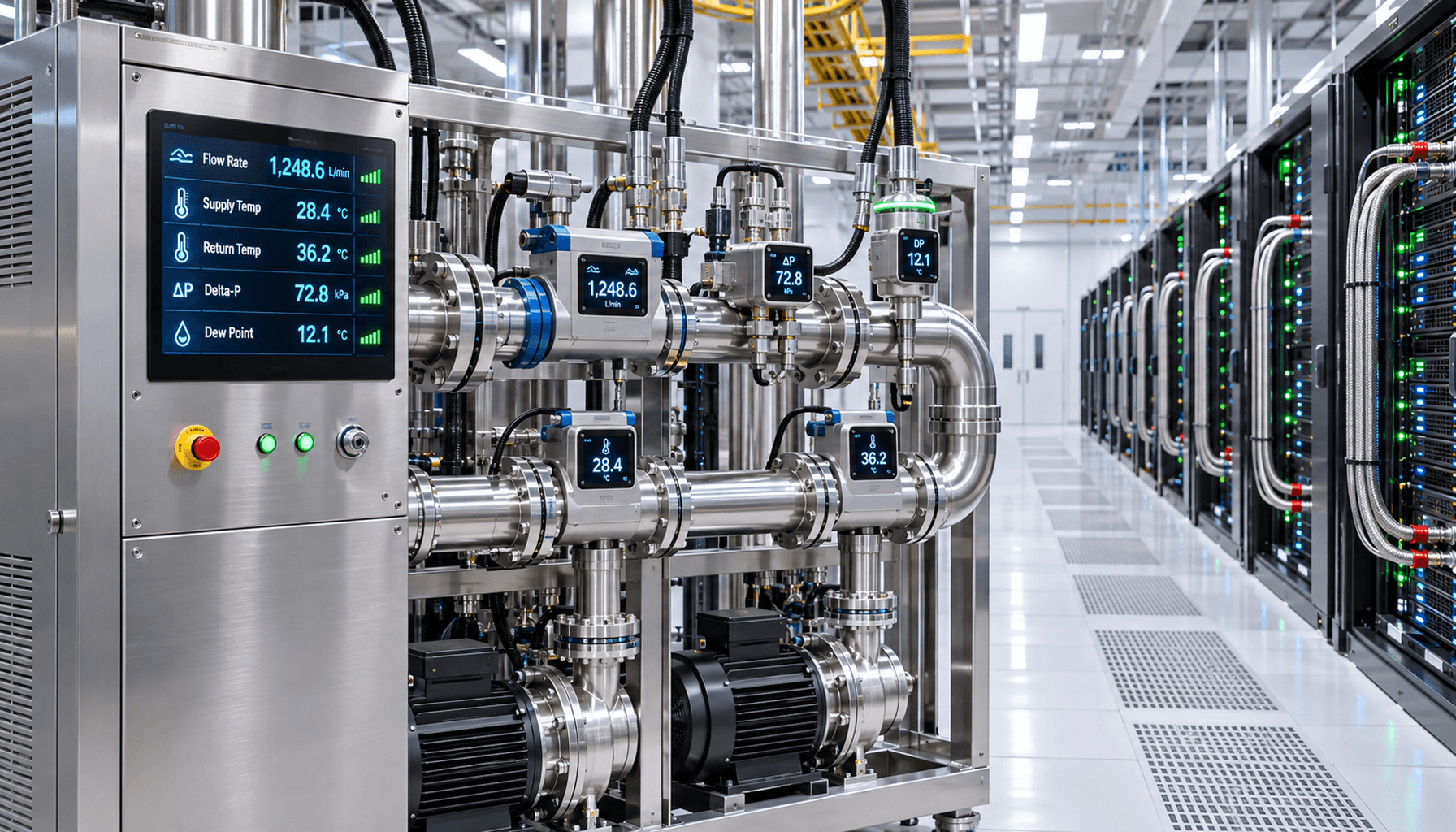
Architectural Paradigm Shift: From Air-Side Envelopes to Dual-Medium Coupled Metrology
Hyperscale artificial intelligence clusters operating at 80 kW to over 150 kW per rack render legacy thermal management paradigms obsolete. Historic facility telemetry focused almost entirely on static aisle differential air pressure, bulk volumetric airflow, dry-bulb temperature, and bulk relative humidity. In contrast, direct-to-chip liquid-cooled architectures require an integrated, dual-medium measurement regime. Thermal energy extraction is concentrated within closed-loop hydronic networks, yet these networks remain thermally and psychrometrically coupled to the adjacent air envelope. Engineers must measure both the fluid transport characteristics within the primary and secondary cooling loops and the microclimatic thermodynamic states surrounding the chassis manifolds, blind-mate couplings, and heat-generating compute boards.
A critical challenge in AI data centers is the severe transient behavior driven by model training checkpointing and bursts of variable-rate distributed inference. System power demand can swing between idle states and maximum thermal design power within hundreds of milliseconds. Such rapid fluctuations produce severe heat flux variations across the cold-plate interface, inducing localized fluid density shifts, acoustic pressure ripples, and thermodynamic lag. Conventional proportional-integral-derivative controllers operating on multi-second polling intervals cannot track these dynamic step-changes, resulting in thermal overshoot at the semiconductor die or mechanical stress across the distribution piping. Modern Coolant Distribution Units must employ sub-second sensor sampling regimes linked to feed-forward control algorithms that predictively modulate pumping displacement and facility three-way control valves prior to steady-state feedback confirmation.
Sub-second hydronic telemetry sampling rates of 100 milliseconds or faster to mitigate thermal overshoot during model checkpoint load transitions
Coupled state-space modeling bridging secondary hydronic heat absorption vectors with local whitespace rack-level microclimate envelopes
Critical Hydronic Metrology: Pressure Transients, Flow Dynamics, and Delta-T Envelopes
Reliable heat extraction across high-density liquid loops depends on precise differential pressure management and advanced cavitation prevention. High-accuracy piezoresistive differential pressure transmitters installed across Coolant Distribution Unit plate heat exchangers, supply-to-return rack headers, and individual chassis flow passages detect localized flow resistance anomalies. Maintaining Net Positive Suction Head at the circulation pump impellers is essential to prevent vapor bubble formation, cavitation erosion, and acoustic vibrations. Furthermore, adequate differential pressure suppresses micro-bubble entrainment within the internal micro-channels of direct-to-chip cold plates, where even localized vapor locking can elevate thermal resistance and trigger semiconductor thermal throttling.
Volumetric and mass flow rates must be measured with extreme accuracy to verify balanced fluid distribution across parallel compute nodes. Inline or non-intrusive clamp-on ultrasonic transit-time flow meters with accuracy ratings of plus or minus 0.5 percent of reading provide real-time fluid velocity data without introducing pressure drops or mechanical wear vectors. This flow measurement enables continuous calorimetric balance calculations where thermal dissipation equals mass flow rate multiplied by specific heat capacity and the differential temperature between supply and return manifolds. Hyperscale operators optimize these parameters to maintain an 8 to 12 degrees Celsius delta-T across cold plates while operating within elevated supply coolant regimes, such as ASHRAE W3 or W4 classifications (30 to 45 degrees Celsius), maximizing compressor-free economizer run hours while keeping semiconductor junction temperatures safely below 85 degrees Celsius.
Transit-time ultrasonic flow instrumentation providing plus or minus 0.5 percent accuracy for continuous per-rack calorimetric heat balance calculations
Piezoresistive differential pressure transmitters configured with sub-10-millisecond response profiles to detect pump cavitation risk and micro-channel restriction
Dew Point Dynamics and Real-Time Condensation Safeguards
The introduction of high-volume liquid circuits into the white space creates a critical failure mode: surface condensation. If secondary loop supply piping, quick-disconnect couplings, or manifold surfaces drop below the local ambient air dew point temperature, water vapor rapidly condenses onto metal surfaces. In a high-voltage, high-amperage compute environment, uncontrolled moisture accumulation induces catastrophic dielectric breakdown, galvanic corrosion, and structural dendrite formation on printed circuit boards. The psychrometric vulnerability is most acute during seasonal transitions, humid ambient weather, or sudden compute load reductions where supply coolant temperatures may dip while the surrounding air retains high moisture content.
To establish an absolute safeguard, thermal architects enforce a dynamic dew point safety buffer. High-precision thin-film capacitive polymer dew point transmitters are placed directly at the rack manifold entry points and within the cooling air path. The Coolant Distribution Unit automation system dynamically calculates the real-time ambient dew point and continuously regulates the secondary fluid supply temperature via three-way mixing valves to maintain a strict minimum threshold of at least 2.0 degrees Celsius above the calculated ambient dew point. During economizer transitions involving variable facility water temperatures, this automated mixing logic prevents overcooling, ensuring cold-plate fluid entry temperatures adjust synchronously with fluctuations in ambient whitespace psychrometrics.
Thin-film capacitive polymer sensing at manifold junctions delivering real-time dew point measurement accuracy within plus or minus 0.2 degrees Celsius
Automated three-way mixing valve trim logic enforcing secondary coolant temperatures strictly greater than or equal to local dew point plus 2.0 degrees Celsius
Fluid Chemistry Metrology: Degradation Tracking and Dielectric Integrity
The thermophysical stability of closed-loop secondary coolants directly dictates heat transfer efficiency and mechanical reliability. Hyperscale deployments predominantly utilize a mixture of 25 percent propylene glycol and 75 percent deionized water treated with organic acid corrosion inhibitor packages, or specialized synthetic dielectric hydrocarbons. Over time, these fluids face chemical degradation. Propylene glycol undergoes thermal cracking under high heat flux, yielding corrosive organic acids like glycolic, formic, and lactic acids that decrease fluid pH and attack cold-plate copper substrates. Simultaneously, corrosion inhibitor packages deplete, leaving dissimilar metals susceptible to aggressive galvanic reactions.
Continuous in-line fluid chemistry metrology replaces periodic manual sampling with continuous automated diagnostics. Dual-electrode or toroidal conductivity sensors track ionic contamination, signaling when electrical conductivity exceeds baseline thresholds (typically 10 microsiemens per centimeter for deionized water formulations), which indicates active corrosion or additive breakdown. In-line optical particle counters and nephelometric turbidity units monitor suspended insoluble particulates, identifying pump impeller erosion, bio-growth, or oxide precipitation before particles can obstruct micro-channel fin gaps smaller than 100 micrometers. Furthermore, continuous digital refractometers track the refractive index to maintain precise glycol ratios, balancing anti-freeze protection and thermal capacity against dynamic fluid viscosity increases.
Continuous in-line electrical conductivity instrumentation enforcing an operational ceiling below 10 microsiemens per centimeter
Inline digital refractometry and optical turbidity monitoring to verify glycol mixture stability and detect micro-particulates prior to cold-plate clogging
Sensor Deployment Topology, Fault Tolerance, and Control Telemetry Integration
A metrology architecture is only as dependable as its spatial topology and mechanical installation integrity. In high-density AI environments, point-of-use sensor placement is mandatory. Temperature sensors must not be confined to bulk fluid pipes; surface-contact resistance temperature detectors must be affixed directly to the bodies of blind-mate quick-disconnect couplings and low-velocity header junctions where stagnant air pockets enhance condensation risk. Critical monitoring parameters, particularly fluid leak detection and volumetric flow rate verification around multimillion-dollar compute clusters, mandate 2-out-of-3 voting logic to eliminate false-positive emergency shutdowns while ensuring complete fail-safe trip coverage.
Telemetry ingestion architectures must handle massive volumes of high-frequency data without introducing control lag. Point-level instrumentation converges at internal Coolant Distribution Unit programmable logic controllers via robust physical layers including RS-485 Modbus RTU and isolated 4 to 20 milliamp current loops. For supervisory integration, these controllers stream edge-processed telemetry up to Data Center Infrastructure Management platforms and facility automated management engines using high-speed protocols such as BACnet/IP, OPC Unified Architecture, and lightweight gRPC streams. This integration permits dynamic feed-forward control algorithms to balance primary facility chiller plants, secondary distribution pumps, and chip-level clock frequencies in unison, preserving hardware reliability and system efficiency.
Fault-tolerant 2-out-of-3 voting architectures implemented across all critical leak detection and flow confirmation channels
Edge telemetry aggregation utilizing deterministic industrial protocols including Modbus RTU, OPC UA, and gRPC for sub-second supervisory ingestion
Engineering Procurement & Technical Desk
For technical datasheets, custom power topology design, or volume export quotations, reach out to HEFENGQI engineers.