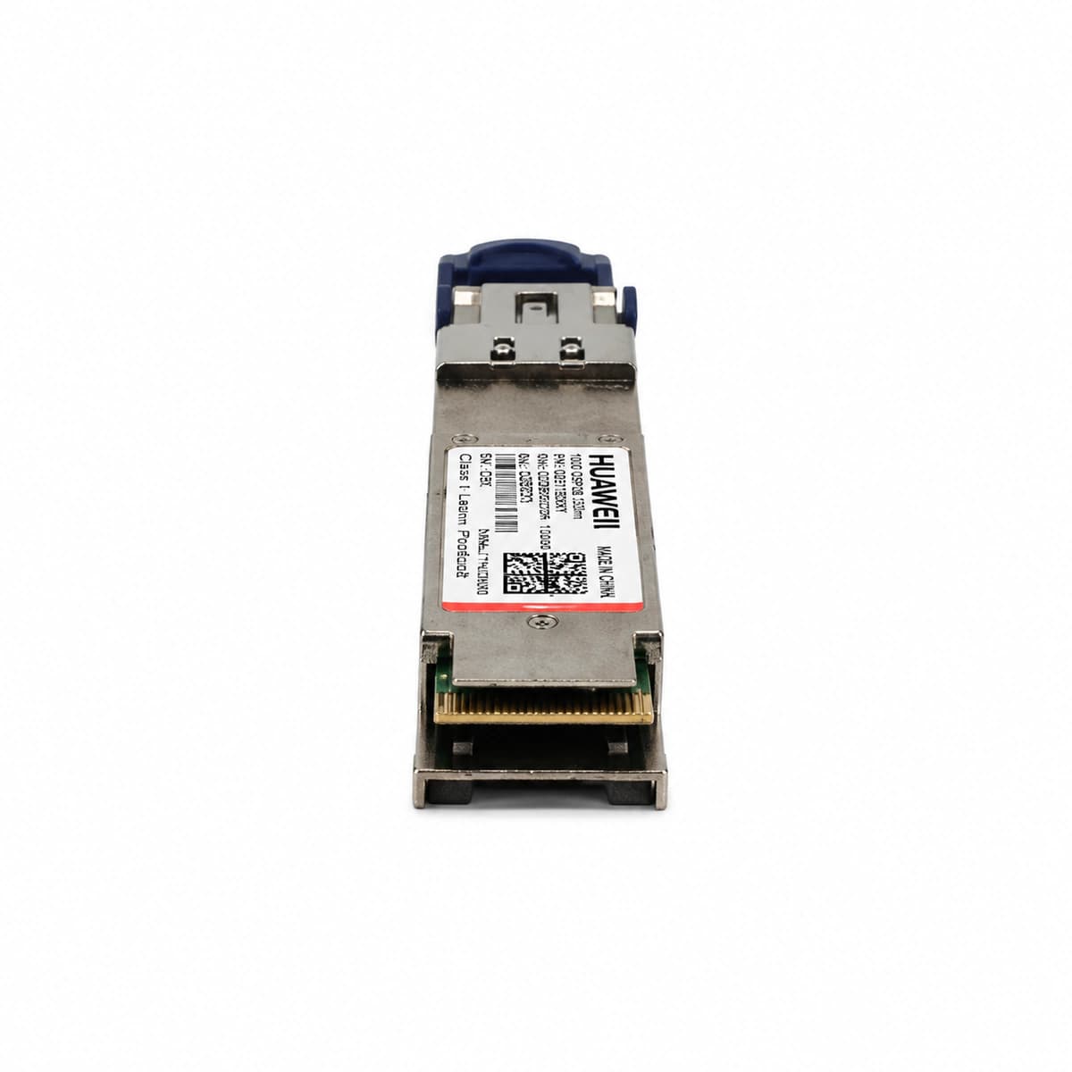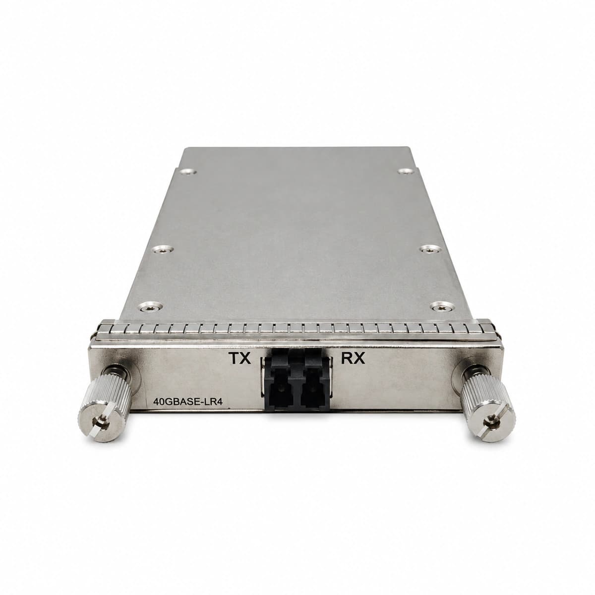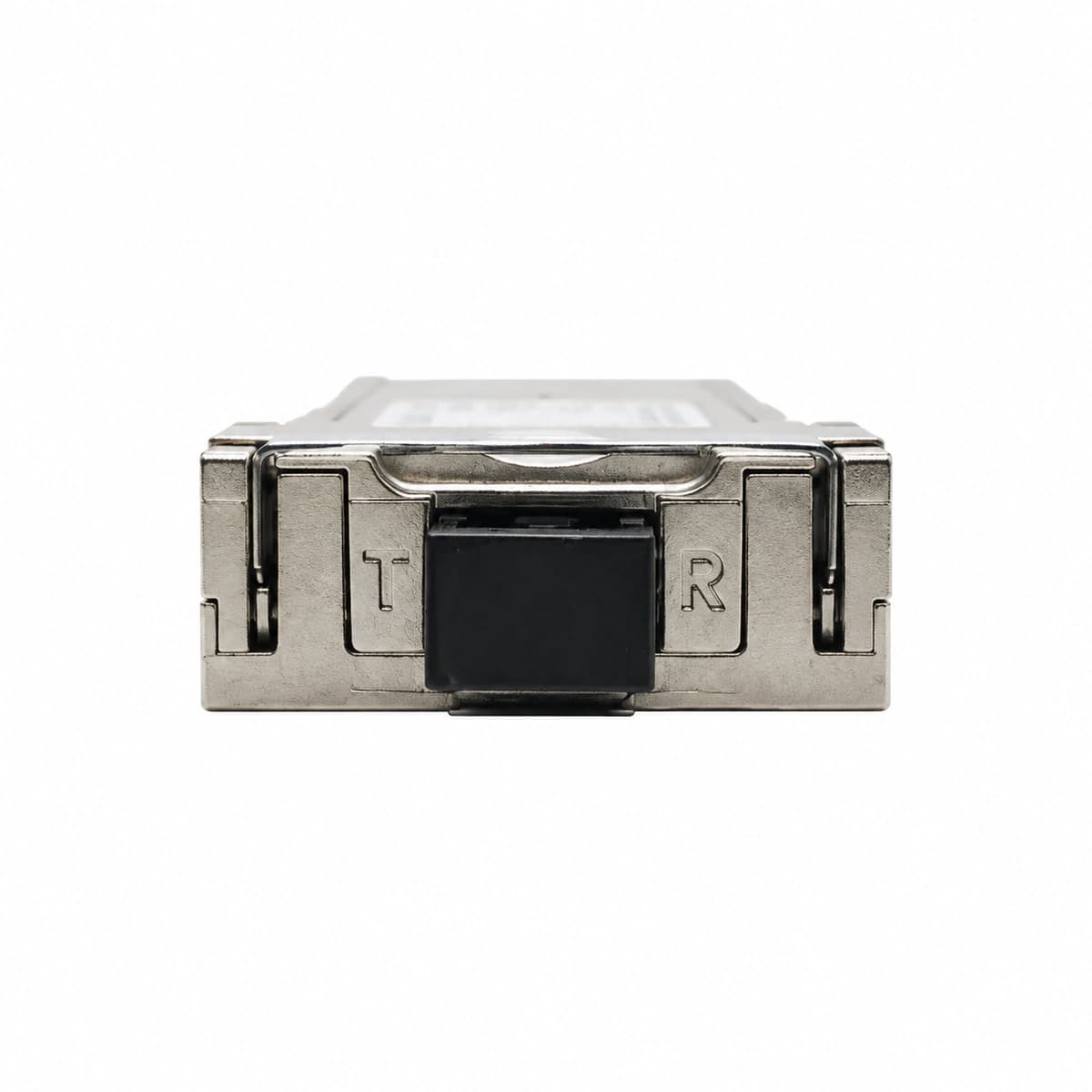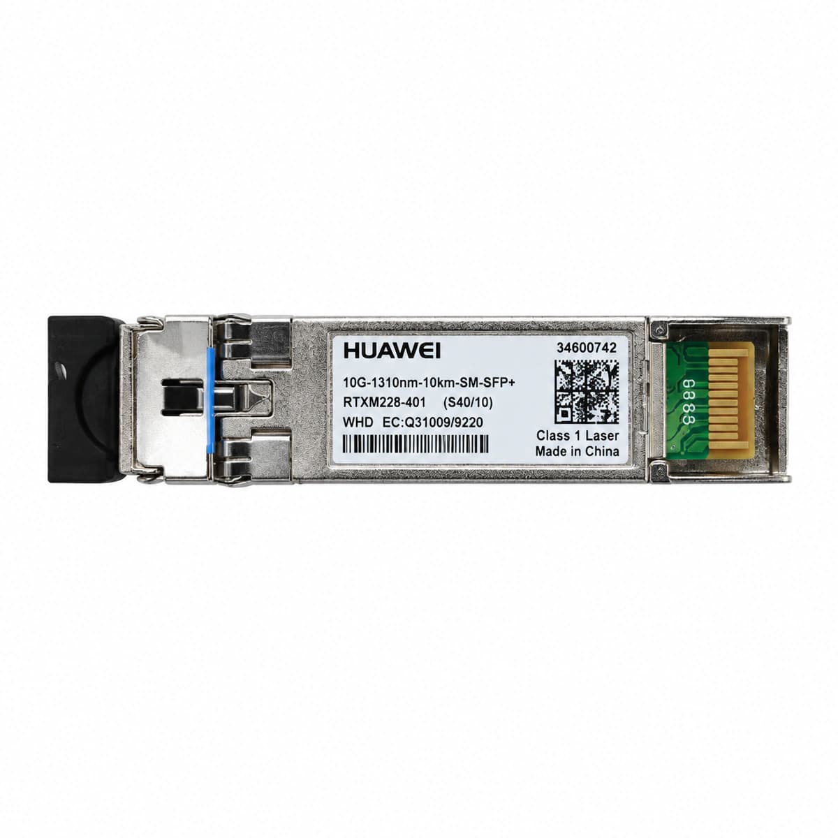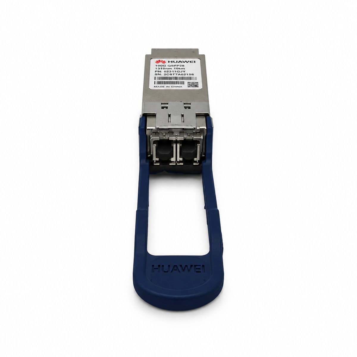
[Engineering Background] In modern AI data center Leaf-Spine architectures and metro transmission backbones, the 100G QSFP28 LR4 (100GBASE-LR4, utilizing 4-lane LAN-WDM around 1310nm with up to 10km reach over single-mode fiber) is among the most widely deployed mission-critical optical transceivers. However, industry diagnostics indicate that over 70% of optical link disruptions—such as intermittent link flapping, high CRC error counts, and optical power alarms—are caused by fiber end-face contamination, incorrect handling, unmanaged optical budget, or switch EEPROM vendor lock-in, rather than internal component failures.
HEFENGQI Optical Interconnect Lab and Technical Support Department present this end-to-end field engineering manual for Huawei 100G QSFP28 LR4 transceivers, detailing fiber cleaning routines, DDM diagnostic reading, optical attenuation calculation, and multi-vendor troubleshooting.
[Step 1: Preparation, Laser Safety, and ESD Controls]
Laser Safety: The 100G QSFP28 LR4 multiplexes four high-power DFB laser channels with an aggregate output up to +4.5dBm (Class 1M). Never look directly into the optical LC bores or fiber connector ferrules without laser safety eye protection.
ESD Protection: Internal high-speed CDRs and PIN/APD arrays are highly vulnerable to electrostatic discharge. Field technicians must wear a grounded wrist strap (1M-ohm series resistance) and handle optics in an ESD-protected zone.
Required Tools: 400X fiber end-face inspection microscope, one-click 1.25mm LC fiber cleaner, lint-free optical wipes with high-purity Isopropyl Alcohol (IPA >= 99.5%), calibrated optical power meter (1310nm), and optical dust caps.
[Step 2: LC Ferrule Inspection & Dry/Wet Combined Cleaning Protocol]
Remove dust plugs only when ready for immediate connection. Never touch the ceramic ferrule with bare hands.
Inspect the ferrule end-face under 400X magnification. If debris, dust particles, or liquid residue are detected within the 9-micron fiber core zone, clean immediately.
Dry Cleaning: Insert the one-click LC cleaner into the optical connector, push gently until the mechanical click sounds, performing a 360-degree rotation wipe.
Wet/Dry Combined Cleaning: For persistent organic or oil stains, apply a micro-droplet of IPA onto the corner of a lint-free wipe, pull the ferrule across at 45 degrees, followed immediately by a dry wipe. Re-inspect until zero particles remain in the core area.
[Step 3: Transceiver Insertion, Latching Mechanism, and Indicator Verification]
Hold the optical transceiver by the bail latch, align the module with the switch port cage ensuring correct orientation.
Push the module smoothly into the cage until an audible click confirms the latching mechanism is securely engaged. Gently pull the latch to ensure it cannot slide out.
Flip the bail latch closed into the locked position.
Monitor the corresponding Port LED: Solid green indicates physical layer synchronization (Link Up); blinking amber or off indicates incomplete handshake or physical misalignment.
[Step 4: Real-time DDM Telemetry & Optical Power Acceptance Criteria]
Access switch telemetry via CLI (e.g., display transceiver verbose or show interfaces transceiver detail) to monitor DDM parameters:
Operating Temperature: Standard commercial range is 0 deg C to 70 deg C. Temperatures above 75 deg C necessitate checking cabinet airflow and fan speeds.
Supply Voltage: Rated at 3.3V, normal operation strictly between 3.13V and 3.47V.
Tx Output Power (Per Lane 0-3): Nominal lane output ranges from -4.3dBm to +4.5dBm, with inter-lane variation under 1.5dB.
Rx Input Power (Per Lane 0-3): Receiver sensitivity limit is -10.6dBm; saturation ceiling is +4.5dBm. If received power drops below -10.0dBm, clean connectors or check fiber loss. For short-distance back-to-back testing where Rx exceeds +2.0dBm, insert 3dB to 5dB fixed optical attenuators to prevent detector burnout.
[Step 5: Multi-Vendor Compatibility & EEPROM Lockout Resolution]
When installing Huawei QSFP28 optics in third-party switches (e.g., Cisco, Arista, or open whitebox switches), the port may trigger an 'unsupported transceiver' warning and place the interface in err-disabled state:
In Cisco environments, bypass via hidden commands: 'service unsupported-transceiver' and 'no errdisable detect cause gbic-invalid'.
HEFENGQI engineering teams provide custom EEPROM re-coding prior to shipment, ensuring seamless hardware plug-and-play across Cisco, Juniper, Arista, H3C, and ZTE platforms.
For tailored optical budget calculations, volume inventory queries, or engineering support, reach out to HEFENGQI via our website or Email: lee@ricewind.com | WhatsApp (+86 17621197907).
Engineering Procurement & Technical Desk
For technical datasheets, custom power topology design, or volume export quotations, reach out to HEFENGQI engineers.