The Centimetric Golden Band: Spectrum Dynamics and Propagation Physics of 7.125–8.4 GHz
The exploratory deployment in Concord, California, marks an architectural pivot toward the upper mid-band, specifically the 7.125–8.4 GHz centimetric window (often categorized within the candidate FR3 range). Operating significantly higher than conventional C-band (3.5–3.8 GHz) allocations, this band exhibits elevated free-space path loss (FSPL), governed by the Friis transmission equation where path attenuation increases quadratically with frequency. In practical outdoor topologies, the path loss penalty ranges from 6 dB to 8 dB over 3.5 GHz baselines. Diffraction efficiency around structural obstacles drops sharply, transitioning propagation mechanisms predominantly toward direct specular reflection, high-order diffuse scattering, and line-of-sight (LOS) links.
Non-line-of-sight (NLOS) penetration characteristics impose strict cell geometry bounds. While 3.5 GHz RF energy can partially penetrate standard building envelopes, 7 GHz signals experience substantial insertion loss: standard low-emissivity (low-E) glass introduces 25 dB to 35 dB of attenuation, while dense drywall and reinforced concrete introduce link margins exceeding 15 dB/wall and 40 dB/wall, respectively. Consequently, field validation confirms an optimal macro-to-user inter-site distance (ISD) yielding a realistic 100-to-200-meter cell radius for high-throughput coverage. This spatial limitation shifts macro sites into hyper-dense co-siting nodes, where beamforming gain from dense active antenna configurations must bridge the propagation deficit.
Link budget design margin: Compensate for +6 dB to +8 dB FSPL penalty over 3.5 GHz through narrow-beam high-gain array synthesis.
Penetration loss parameterization: Budget for 30 dB minimum insertion loss on metallized architectural glass and concrete partitions.
Coverage radius constraint: Scale dense urban cell radii between 100 m and 200 m to preserve 64-QAM/256-QAM demodulation SNR.
400 MHz Channel Aggregation: Baseband Signal Processing Complexity and eCPRI Interconnects
Aggregating 400 MHz of contiguous or multi-carrier spectrum over a single physical sector introduces unprecedented digital baseband computational complexity. The Fast Fourier Transform (FFT) processing pipelines must scale proportionally to handle 4,096-point or higher FFT sizes over compressed symbol durations without introducing subcarrier inter-carrier interference (ICI). Massive matrix inversions required for Zero-Forcing (ZF) or Minimum Mean Square Error (MMSE) multi-user MIMO (MU-MIMO) beamforming scale on the order of O(K³), where K represents concurrent spatial layers. This compute density requires dedicated ASIC and FPGA acceleration clusters inside the Baseband Unit (BBU), driving baseband thermal design power (TDP) per subrack above 1.2 kW.
This expanded channel bandwidth fundamentally disrupts traditional fronthaul transport. Under eCPRI (Option 7-2x) split architectures, the payload throughput scaling is a direct function of bandwidth, subcarrier spacing, and antenna branch quantization bits. Transmitting 400 MHz of user and control plane traffic across 64T64R or 256-element arrays produces fronthaul data rates that surpass the capacity of common 25G SFP28 transceivers. Network operators must transition to 100G and 200G optical links utilizing Pulse Amplitude Modulation 4-level (PAM4) QSFP28/QSFP56 transceivers. At these line rates, chromatic dispersion penalties over standard G.652 single-mode fiber (SMF) require low-latency forward error correction (FEC) engines, with strict eCPRI one-way transport delay budgets constrained to less than 100 microseconds.
Optical transport specification: Deploy 100G/200G PAM4 (QSFP28/56) industrial-temperature (-40°C to +85°C) optics for fronthaul links.
Fronthaul latency constraint: Restrict total one-way optical and serialization delay to < 100 µs to maintain hybrid ARQ timing.
BBU compute density provisioning: Accommodate subrack processing loads exceeding 1.2 kW with high-throughput N+1 forced-air cooling.
High-Order Massive MIMO and GaN RF Power Amplifiers: Thermal Dissipation and Efficiency
Achieving link parity at 7 GHz requires high-element Active Antenna Units (AAUs), scaling beyond standard 64T64R matrices to 256-element or 512-element sub-array architectures. The corresponding physical aperture size shrinks due to the smaller wavelength (λ ≈ 3.75 cm to 4.2 cm), packing active RF components into a compact volumetric envelope. Traditional Silicon LDMOS power amplifiers fail at these frequencies due to severe parasitic capacitances and transition-frequency limits. Consequently, RF front-ends are transitioning to Gallium Nitride on Silicon Carbide (GaN-on-SiC) High Electron Mobility Transistors (HEMTs), operating at elevated drain voltages (Vds = 48V to 65V).
GaN devices deliver the required Power-Added Efficiency (PAE > 50%), yet linearized output power over a broad 400 MHz instantaneous bandwidth presents extreme engineering hurdles. Digital Pre-Distortion (DPD) systems must capture third- and fifth-order intermodulation products across bandwidths exceeding 1.2 GHz to 2.0 GHz, requiring multi-gigasample-per-second feedback ADCs. Despite high PAE, the aggregate power dissipation of hundreds of integrated RF chains, digital beamforming ASICs, and low-noise amplifiers (LNAs) concentrates 1.8 kW to 2.5 kW of continuous thermal waste per sector. Tower-mounted thermal designs require advanced multi-cavity vapor chambers, phase-change thermal interface materials (TIM), and optimized natural convection heat-pipe fin arrays to prevent junction temperatures from exceeding the 150°C reliability ceiling.
RF semiconductor choice: Implement GaN-on-SiC HEMT power stages with PAE ≥ 50% at operating drain voltages of 48V–65V DC.
DPD bandwidth scaling: Verify predistortion feedback receiver bandwidth supports ≥ 1.2 GHz instantaneous linearization loop.
Thermal load tolerance: Engineer tower-top passive cooling for 1.8 kW–2.5 kW heat flux per AAU, keeping silicon/GaN Tj < 150°C.
Macro Base Station -48V DC Power Upgrades: High-Efficiency Rectifiers and I²R Loss Mitigation
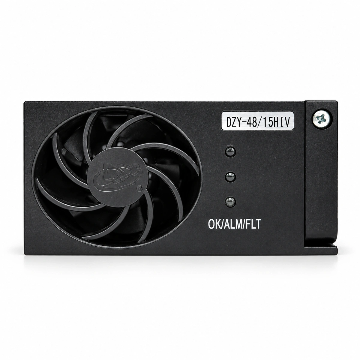
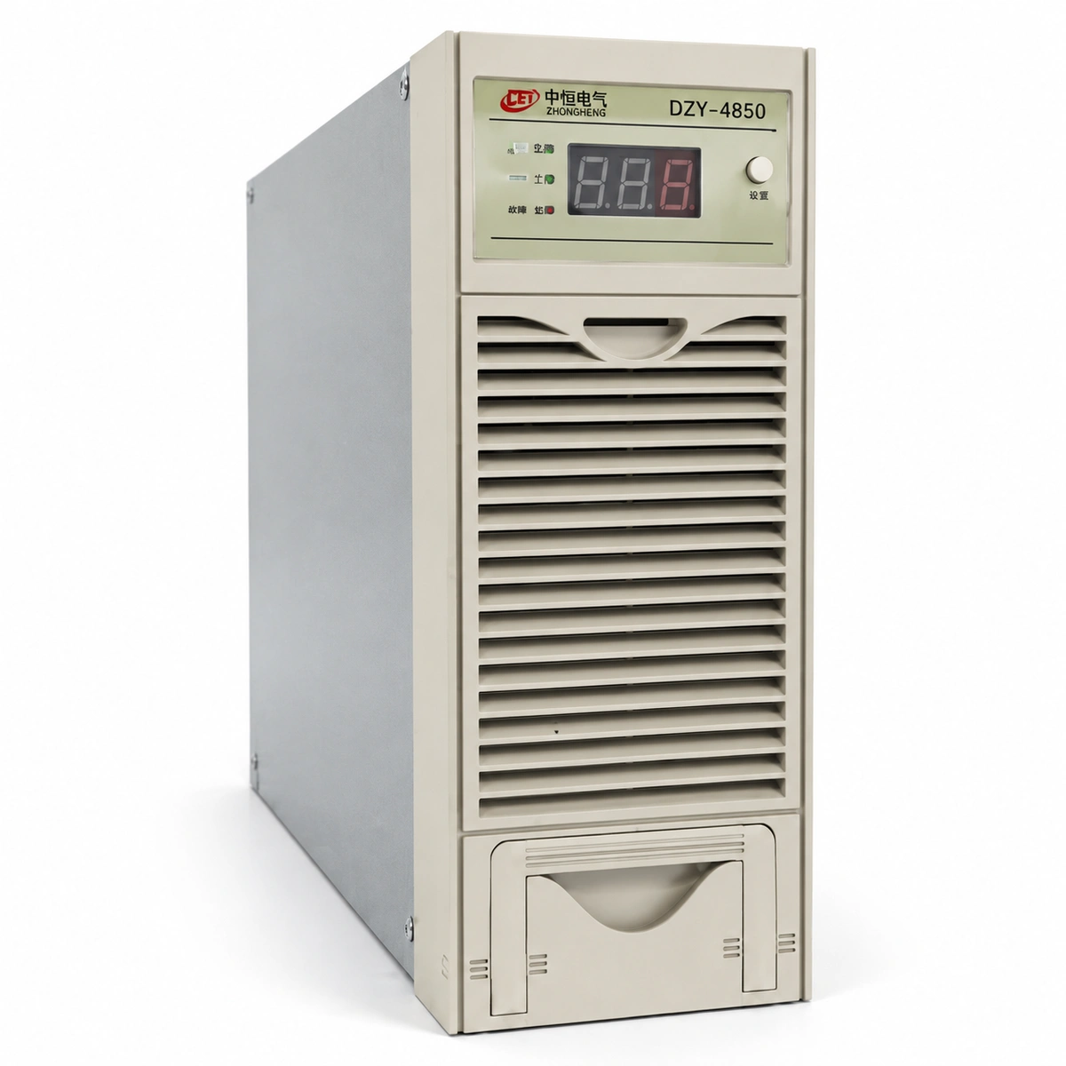
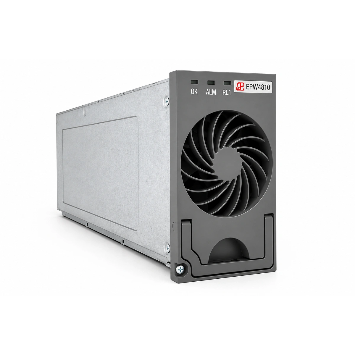
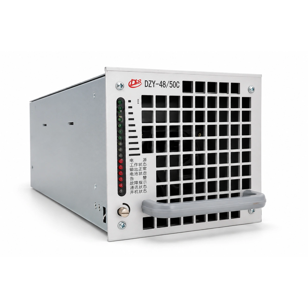
Overlaying a 7 GHz pre-6G active layer onto an existing macro site—already operating low-band (700/850 MHz), mid-band (PCS/AWS), and 3.5 GHz C-band gear—forces total site DC consumption past the 12 kW to 18 kW threshold. This load profile overwhelms legacy -48V DC power enclosures. Central rectifiers must be upgraded to modular switch-mode topologies delivering 96.5% to 98% titanium-class conversion efficiencies. High efficiency directly lowers internal cabinet cooling requirements, reducing auxiliary HVAC power consumption and preventing thermal cascading during high-ambient outdoor operating cycles.
The transmission of high direct currents over 40 to 60 meters of tower-run cabling introduces critical resistive (I²R) power losses and terminal voltage droop. Supplying 2.5 kW to a 7 GHz AAU at nominal -48V DC implies line currents exceeding 52 A per sector head. Standard 10 mm² copper conductor trunks incur severe voltage drops that risk violating the AAU minimum input voltage threshold (typically -40.5V DC to -42V DC). Telecom power systems address this challenge through two primary topologies: deploying heavy-gauge copper trunks (25 mm² to 35 mm²) or integrating modular DC-DC boost up-converters within the ground cabinet. By up-converting the nominal bus to -57V DC for the remote runs, line current drops proportionally, suppressing resistive losses by up to 28% and ensuring stable, compliant voltage at the masthead.
Rectifier module efficiency: Deploy modular switch-mode rectifiers achieving ≥ 97% thermal-electrical efficiency profile.
Voltage regulation optimization: Implement a boosted -57V DC distribution bus to limit tower cabling voltage drop to < 5%.
Cable cross-section sizing: Specify 25 mm² to 35 mm² shielded copper conductors for high-power AAU feeders exceeding 45 meters.
Dynamic Energy Storage and Peak Shaving: Lithium Iron Phosphate (LiFePO4) Battery Architecture
The substantial peak loads introduced by 400 MHz centimetric transmission invalidate traditional Valve-Regulated Lead-Acid (VRLA) batteries due to their low volumetric energy density, slow recharge profiles, and severe cycle life degradation under rapid discharge rates. Modernized sites demand 48V, 100Ah/150Ah smart Lithium Iron Phosphate (LiFePO4) energy storage systems (BESS). LiFePO4 chemistry provides deep cycle endurance (> 4,000 cycles at 80% Depth of Discharge) and high C-rate discharge capability, critical for maintaining macro operation when concurrent 5G/6G spatial streams saturate site compute and RF stages.
Beyond reserve autonomy, the integration of distributed intelligent Battery Management Systems (BMS) with high-speed CAN/Modbus communication links introduces dynamic peak shaving. Dynamic energy management algorithms synchronized with the baseband scheduler monitor utility input power in real time. During peak tariff hours or localized grid instability, the power plant dynamically draws supplemental current from the LiFePO4 packs to clip commercial AC grid spikes without throttling 7 GHz RF output power. This architecture minimizes utility demand charges and ensures continuous operation over constrained utility interconnect drops.
Battery chemistry transition: Mandate LiFePO4 chemistry with ≥ 4,000 cycle capability at 0.5C discharge rates and 80% DoD.
BMS data telemetry: Interface battery management units via CAN/Modbus to macro site controllers for real-time state-of-charge tracking.
Peak-shaving configuration: Program dynamic threshold shaving to dispatch battery capacity when site load surpasses grid breaker limits.
Site Deployment and Grounding Engineering: Tower-Top AAU Co-Siting and Transient Surge Protection
Physical deployment of centimetric AAUs presents severe structural and electro-mechanical challenges on existing multi-tenant macro masts. The large physical profile of integrated 256T256R array packages, combined with substantial heat sinks, increases tower-top aerodynamic drag (effective projected area, EPA). Structural analysis must verify that tower mounting brackets, pipe mounts, and structural lattice sections withstand extreme wind loads without deflection that would alter the narrow azimuth and tilt pointing vectors required for 7 GHz narrow-beam transmission.
Furthermore, mounting high-value, active GaN RF units at masthead heights amplifies vulnerability to direct and induced atmospheric lightning surges. Robust transient voltage mitigation demands coordinated multi-stage surge protection devices (SPDs). Type 1 (Class I) SPDs featuring spark gap or heavy-duty metal oxide varistor (MOV) technologies (impulse current Iimp ≥ 25 kA 10/350 µs) must guard the AC service entrance and base DC distribution cabinets. Type 2 (Class II) SPDs (nominal discharge current In ≥ 20 kA 8/20 µs) must sit directly adjacent to the masthead DC inputs and hybrid junction breakout boxes. All metal chassis, cable shielding, and mounting brackets must bind to a single-point grounding bus with low-impedance copper conductors (≥ 16 mm² to 25 mm²), maintaining an integrated earth termination resistance below 5 Ohms.
Structural load compliance: Validate mount stiffness to maintain narrow 7 GHz beam pointing within ±0.5° under peak wind conditions.
Multi-stage surge suppression: Install Class I SPDs (Iimp ≥ 25 kA) at power demarcation and Class II SPDs at tower-mounted AAUs.
Ground network impedance: Maintain low-impedance earth termination (< 5 Ω) via multi-grounded 25 mm² stranded copper ring bonding.
Engineering Procurement & Technical Desk
For technical datasheets, custom power topology design, or volume export quotations, reach out to HEFENGQI engineers.