The Regulatory Paradigm Shift: NERC Project 2026-02 and the 50 MW / 100 kV Bulk Grid Mandate
The rapid deployment of hyperscale computational architectures dedicated to artificial intelligence training and high-performance computing (HPC) has exposed structural vulnerabilities in traditional transmission-level interconnection practices. Historically, large industrial electrical loads were categorized as passive, aggregate demands displaying predictable load-duration curves and continuous mechanical damping. Under North American Electric Reliability Corporation (NERC) Project 2026-02, initiated in response to a Level 3 Reliability Alert, computational facilities featuring an aggregate capacity of 50 MW or greater and interconnecting at transmission-level voltages of 100 kV or higher are subject to mandatory Bulk Electric System (BES) reliability governance. This regulatory recalibration transitions large-scale data center operators from non-registered commercial consumers into fully regulated entities accountable to regional Balancing Authorities (BAs), Transmission Planners (TPs), and Reliability Coordinators (RCs).
The primary catalyst for this mandate is the documented operational risk posed by uncoordinated active power variations across regional footprints. A sudden tripping or synchronization step-change within a multi-hundred-megawatt compute cluster behaves identically to a transmission-level loss-of-generation or loss-of-load event. When multiple clusters experience synchronous software-driven interrupts or busbar disturbances, the simultaneous drop in power demand induces localized overfrequency excursions and steep Rate of Change of Frequency (RoCoF) trajectories that can exceed 0.5 Hz/s. Under NERC Project 2026-02, these computational facilities must adhere to standardized modeling, reporting, and operational protocols—aligning their interconnection compliance with FAC-001/002, MOD-026/027, and PRC-024 reliability standards to safeguard bulk power stability.
Mandatory registration threshold applied at aggregate capacity >= 50 MW at POI voltages >= 100 kV.
Formal integration into regional Balancing Authority dispatch, contingency reserves, and emergency load curtailment hierarchies.
Strict adherence to maximum localized RoCoF thresholds (< 0.5 Hz/s) under single-contingency cluster trip events.
Computational Load Transients: Mitigating Sub-Second AI Training Load Dumps and Severe di/dt Surges
Distributed machine learning workloads introduce an unprecedented operational dynamic known as workload synchronization cycling. During model training across tens of thousands of accelerated computing nodes (GPUs/TPUs), execution phases alternate between intense tensor arithmetic and global communication operations, such as AllReduce or AlltoAll data exchanges. During computation phases, modern switched-mode power supply systems draw peak current; conversely, when collective communication barriers or unexpected distributed training exceptions occur, active power demand can instantaneously plummet from 100% full-load capacity to nominal idle levels (10% to 15%) within 10 to 50 milliseconds. The resultant di/dt current step excites high-frequency transient overvoltages (TOVs) and triggers severe active power oscillations across the point of common coupling (PCC).
Mitigating these catastrophic active power step-changes requires active behind-the-meter buffering topologies at the facility collector bus. Power systems engineers are deploying multi-tiered dynamic response architectures that integrate high-speed dynamic load banks (chopper-controlled resistor banks) and hybrid energy storage systems (fast-ramping lithium-ion BESS paired with electrostatic double-layer ultracapacitors). The fast-acting dynamic shunts, modulated via insulated-gate bipolar transistors (IGBTs) or integrated gate-commutated thyristors (IGCTs), detect the onset of computational load dumps and autonomously switch in dummy resistive loads within 5 to 10 milliseconds. This buffers the step-change until utility-side automatic generation control (AGC) and governor response mechanisms can re-establish generation-demand equilibrium without triggering system-wide frequency relays.
Active power slew-rate clamping to constrain rate-of-change (di/dt) to < 5 MW/ms at the transmission interface.
Autonomous dynamic load bank engagement capable of absorbing 100% of dropped load within <= 10 ms for a minimum duration of 3 seconds.
Behind-the-meter hybrid BESS and ultracapacitor deployment sized to provide transient active power substitution for >= 30 seconds.
Electromagnetic Transient (EMT) Modeling: Validating Sub-Synchronous Resonance and Weak-Grid Interconnects
Traditional interconnection studies relying exclusively on positive-sequence, root-mean-square (RMS) tools, such as PSS/E or PowerWorld, are mathematically incapable of representing the sub-cycle converter dynamics inherent to large computational campuses. Large-scale data centers are powered almost entirely by active front-end (AFE) rectifiers, phase-shifted bridge converters, and uninterruptible power supply (UPS) systems utilizing fast inner-loop current controllers and phase-locked loops (PLLs). Under NERC Project 2026-02, interconnection developers must provide high-fidelity Electromagnetic Transient (EMT) models, developed on platforms such as PSCAD/EMTDC, which utilize compiled OEM controller firmware (white-box or validated black-box) to simulate detailed point-on-wave non-linearities and switching dynamics down to microsecond intervals.
A critical focus of these EMT evaluations is verifying the absence of Sub-Synchronous Control Interaction (SSCI) and high-frequency resonances within weak-grid environments characterized by low Short-Circuit Ratios (SCR < 2.0). When connected near electrically distant generation or series-compensated transmission corridors, the high-bandwidth control loops of AFE rectifiers can present negative damping across sub-synchronous frequency bands (5 Hz to 45 Hz). EMT studies must validate that converter control topologies maintain positive phase and gain margins across all operating envelopes, demonstrating that interactions with nearby inverter-based resources (IBRs) or series-compensated circuits do not produce undamped torsional oscillations or converter instability.
Submission of OEM-certified, controller-in-the-loop EMT models (PSCAD/EMTDC) prior to interconnection approval.
Impedance scan validation proving net-positive damping from 0.1 Hz to 2.5 kHz across extreme N-1 and N-2 grid topologies.
Demonstrated computational load stability under weak-grid conditions down to an effective Short Circuit Ratio (SCR) of <= 1.5.
Ride-Through Governance: Low-Voltage (LVRT) and Frequency Ride-Through Tuning for Power Electronic Rectifiers
A profound vulnerability exposed during transmission fault analyses was the tendency of hyperscale computing facilities to trip off-line during distant, normally cleared transmission faults. Historically, server-level power supply units (PSUs) and commercial-grade UPS rectifiers were configured with aggressive instantaneous protection setpoints, disconnecting whenever incoming AC voltage dropped below 0.85–0.90 per-unit (p.u.) for durations as brief as 20 to 50 milliseconds to protect intermediate DC-bus capacitors. Consequently, single-line-to-ground or three-phase faults on remote transmission lines led to the aggregated loss of hundreds of megawatts of computational load, transforming localized transmission voltage dips into widespread bulk system frequency disturbances.
NERC Project 2026-02 amends ride-through performance requirements to mandate rigorous Low-Voltage Ride-Through (LVRT) and Frequency Ride-Through (FRT) envelopes aligned with PRC-024 revisions. Rectifier front ends and industrial UPS topologies must now provide continuous Zero-Voltage Ride-Through (ZVRT) capabilities, remaining connected during symmetric and asymmetric terminal voltage drops down to 0.0 p.u. for up to 150 milliseconds at the high-voltage Point of Interconnection (POI). Furthermore, active converter controls must inject dynamic reactive current during voltage sags—governed by proportional k-factors (Iq injection >= 2.0 p.u. per unit voltage drop)—to support the recovery of the bulk transmission voltage, while remaining operational through frequency deviations spanning 56.5 Hz to 62.0 Hz.
Full ZVRT compliance: continuous grid connection at 0.0 p.u. POI terminal voltage for >= 150 ms without tripping.
Dynamic reactive current delivery: Iq response initiated within <= 20 ms with a current injection gain of k >= 2.0.
Prohibition of sub-cycle undervoltage tripping within the continuous operating profile of 0.88 to 1.10 p.u. AC voltage.
Real-Time Synchrophasor Telemetry: PMU Integration, High-Speed SCADA, and Deterministic Curtailment
Operational visibility of massive computational nodes requires upgrading utility telemetry infrastructure from legacy, low-speed supervisory control and data acquisition (SCADA) systems to high-speed synchrophasor networks. Standard SCADA polling rates of 2 to 4 seconds fail to detect intra-second power swings, oscillatory modes, or sub-second load shedding events. Transmission Operators now mandate the installation of dual-redundant, GPS-synchronized Phasor Measurement Units (PMUs) compliant with IEEE C37.118 at the facility collector substations. These units must stream time-aligned voltage, current, active power, reactive power, and frequency data at continuous sampling rates of 60 frames per second directly into utility Energy Management Systems (EMS) and dynamic state estimators.
This real-time telemetry architecture underpins automated, deterministic Remedial Action Schemes (RAS) and Fast Frequency Response (FFR) platforms. To prevent cascading line thermal overloads during sudden transmission loss contingencies, data center Energy Management Systems must interface with utility dispatch centers via deterministic, cryptographically secure industrial protocols such as IEC 61850 GOOSE and DNP3 Secure Authentication. In scenarios requiring urgent system re-balancing, pre-negotiated direct load curtailment signals are executed autonomously, commanding computational workloads to throttle processor frequencies and shedding active power consumption within 50 milliseconds of signal confirmation.
Redundant IEEE C37.118-compliant PMU telemetry streaming at 60 Hz reporting rates to regional TOP control rooms.
Deterministic inter-substation Remedial Action Scheme (RAS) execution latency <= 50 ms from trigger initiation.
Secure bidirectional utility-to-campus communication architectures utilizing encrypted IEC 61850 GOOSE over dedicated fiber-optic channels.
Substation Electrical Topology: Deploying Synchronous Condensers, STATCOMs, and Hybrid Dynamic Shunts
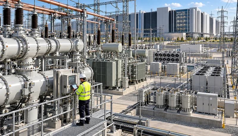
Connecting gigawatt-scale computational campuses to high-voltage transmission grids (e.g., 230 kV, 345 kV, or 500 kV stepped down to 34.5 kV or 13.8 kV distribution topologies) requires specialized substations engineered to deliver physical inertia and fast dynamic reactive support. In weak grid nodes, the massive concentration of non-synchronous converter loads depresses system strength and increases localized fault impedance. To address this, transmission planners and large campus developers are co-locating utility-scale synchronous condensers within collector substations. These machines deliver genuine physical rotational inertia (inertia constant H >= 3.5 seconds) and inject massive short-circuit currents during faults, elevating the local Short-Circuit Ratio (SCR >= 2.5) and mitigating voltage distortion caused by high harmonic loads.
To achieve comprehensive stability, modern substation topologies pair synchronous condensers with modular multi-level converter (MMC) Static Synchronous Compensators (STATCOMs) to form hybrid dynamic compensation networks. While synchronous condensers furnish physical inertia and deep fault current, the STATCOM provides sub-cycle reactive power compensation with closed-loop response times under 20 milliseconds. This hybrid layout actively suppresses transient overvoltages resulting from sudden computational load dumps, provides fine-grained sub-cycle voltage regulation, and filters high-order switching harmonics. Supported by dual-feed, redundant transmission tie-lines and modern bus differential protection schemes, this substation architecture ensures strict compliance with NERC reliability standards while insulating the regional grid from compute-induced volatility.
Substation physical inertia contribution: target H-factor >= 3.5 s via synchronous condenser deployment.
STATCOM reactive power response latency <= 20 ms across full inductive-to-capacitive dynamic range.
Dual-feed redundant transmission layout engineered to maintain full facility operational capacity under N-1 contingency conditions.
Engineering Procurement & Technical Desk
For technical datasheets, custom power topology design, or volume export quotations, reach out to HEFENGQI engineers.