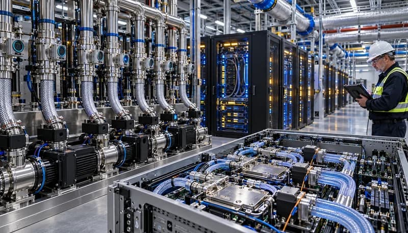
The Thermal Threshold: Why 100 kW+ Megawatt AI Clusters Render Static Hydraulic Balancing Obsolete
Modern artificial intelligence accelerators, driven by dense Multi-Chip Modules (MCM) and 2.5D/3D packaging, have escalated rack-level thermal envelopes beyond 100 kW, with multi-rack training topologies routinely scaling to megawatt densities. Individual compute silicon packages exhibit baseline Thermal Design Power (TDP) figures exceeding 700 W to 1000 W, concentrating heat flux densities past 100 W/cm² across the die-to-cold-plate interface. Legacy hydronic architectures rely on static balance: factory-set flow orifices, calibrated balancing valves, and uniform manifold sizing configured under steady-state assumptions. In contrast, AI inference bursts and transformer training epochs introduce microsecond-scale power transience, causing localized thermal step functions of hundreds of kilowatts that outpace thermal inertia in cold-plate copper skived-fin arrays.
Static hydraulic networks suffer catastrophic thermal degradation under these transient regimes. Because water-glycol and deionized water mixtures exhibit temperature-dependent kinematic viscosity, high-heat compute trays experience localized fluid thinning, which reduces local hydraulic impedance and pulls disproportionate mass flow away from adjacent, highly stressed nodes. This hydraulic cross-talk triggers rapid boiling margins or thermal throttling on starved compute dies. Mitigating such thermal instability requires abandoning coarse, over-provisioned bulk flow regimes in favor of deterministic, real-time dynamic hydronics capable of autonomously adjusting fluid delivery at the sub-rack and tray level.
Dissipate localized heat fluxes exceeding 100 W/cm² at the package level without exceeding critical junction temperatures (Tj < 85°C).
Bound transient hydronic response times to under 200 ms to arrest thermal runaways caused by microsecond compute step loads.
Eliminate hydraulic flow distribution variance to maintain less than ±3% deviation across parallel cold-plate branches.
Real-Time Pump Dynamics: Field-Oriented Motor Control (FOC) and High-Frequency GaN Power Stages in CDUs
Coolant Distribution Units (CDUs) are transitioning from basic fixed-displacement or primitive scalar (V/f) variable-speed pumping assemblies to closed-loop Field-Oriented Control (FOC) multi-phase motor systems. By vectorizing stator currents into orthogonal torque-producing (Iq) and flux-producing (Id) components, FOC microcontrollers eliminate low-frequency torque ripple, suppress mechanical acoustic harmonics, and deliver instantaneous torque response. This precise control allows redundant primary and secondary centrifugal pumps to dynamically track transient system curve shifts without inducing hydraulic hammer or pressure surges across fragile quick-disconnect (QD) couplings.
Simultaneously, the CDU power inverter stage is undergoing a profound paradigm shift: replacing legacy silicon IGBTs and superjunction MOSFETs with wide-bandgap Gallium Nitride (GaN) High-Electron-Mobility Transistors (HEMTs). GaN devices operate at switching frequencies exceeding 100 kHz with virtually zero reverse recovery charge (Qrr), slashing inverter switching losses by up to 2% and decreasing the volumetric envelope of output inductors and capacitors by more than 60%. This power density enables compact, hot-swappable CDU pump modules operating directly from 48V DC, 400V DC, and emerging 800V HVDC microgrid rails, establishing maximum hydronic work output within standardized Open Rack architectures.
Implement high-frequency (>100 kHz) GaN power stages achieving pump inverter electrical conversion efficiencies above 98.5%.
Deploy real-time Field-Oriented Control loops delivering sub-millisecond dynamic torque adjustment during sudden flow demand spikes.
Transition CDU pumping power distribution to 400V or 800V DC rails to reduce I²R conductor losses and eliminate bulk AC transformers.
Granular Tray-Level Flow Throttling: Linear Modulating Valves vs. Bulk Manifold Distribution
Distributing liquid coolant purely through rack-level bulk manifolds results in severe over-cooling of lightly loaded trays and precarious thermal margins on heavily utilized accelerators. Modern architectures integrate linear modulating servo valves directly into the fluid inlet of each server tray. Moving beyond binary on/off solenoids, these multi-turn stepper or piezo-actuated needle/globe valves provide precise volumetric flow throttling across a continuous operational stroke. With actuation slew rates under 50 ms, the system adjusts local mass flow rates (ṁ) in direct synchronization with on-die telemetry, matching heat generation on a tray-by-tray basis.
Granular throttling introduces complex hydraulic cross-coupling: modulating valve position at Tray A changes the system pressure drop (ΔP), which inevitably alters flow velocities through Trays B through N unless actively compensated. To decouple these interactions, hyperscale racks incorporate dynamic Pressure-Independent Control Valves (PICVs) or localized algorithmic feed-forward compensation loops. These hydronic controls isolate tray-level flow variations from the main manifold pressure gradient, stabilizing upstream CDU pump operating points while ensuring that compute nodes receive deterministic fluid delivery irrespective of adjacent valve actuations.
Specify linear modulating control valves with sub-50ms full-stroke actuation slew rates to capture workload-driven thermal transients.
Ensure wide throttling rangeability (>50:1) to precisely modulate mass flow between idle and peak accelerator operational states.
Integrate pressure-independent dynamic balancing logic to prevent hydronic cross-talk across parallel server sleds.
Non-Invasive Instrumentation: Ultrasonic Transit-Time Flow Sensing and Capacitive Leak Arrays
Traditional inline instrumentation—such as turbine flowmeters, vortex shedders, and differential pressure orifice plates—introduces severe vulnerabilities into high-density secondary cooling loops: parasitic head losses, particulate fouling risks, and added mechanical joints that multiply leak failure points. Hyperscale liquid loops are shifting toward non-invasive, clamp-on ultrasonic transit-time flowmeters. By projecting bidirectional acoustic pulses through the pipe wall at frequencies between 1 MHz and 4 MHz, these sensors compute the differential time-of-flight (Δt) along the flow vector, delivering high-precision volumetric flow telemetry within ±1.5% accuracy across diverse liquid viscosities without fluid-wetted seals.
Leak mitigation architectures have evolved from passive, slow-acting resistive moisture ropes toward multi-zone capacitive sensing ribbons and localized dielectric arrays. Resistive ropes suffer from continuous hygroscopic degradation, high false-positive rates from condensation, and an inability to pinpoint micro-droplet coordinates. In contrast, multi-channel capacitive ribbons detect shifts in localized dielectric permittivity caused by sub-milliliter fluid volumes in under 500 ms. Interfaced with differential ambient relative humidity (ΔRH) sensors, these systems isolate true fluid breaches from ambient humidity excursions, enabling automated, localized chassis isolation before catastrophic short-circuits occur.
Enforce clamp-on ultrasonic transit-time flow telemetry to achieve ±1.5% volumetric precision without breaching fluid boundaries.
Deploy continuous capacitive ribbon arrays capable of detecting <0.1 mL dielectric or water-glycol liquid releases within 500 ms.
Eliminate intrusive inline mechanical sensors across the secondary loop to reduce potential leak points by more than 40%.
Edge Sensor Fusion: Multimodal ΔP/ΔT/Acoustic Analytics for Predictive Cavitation and Failure Mitigation
Deterministic reliability in megawatt-scale direct liquid cooling loops depends on edge sensor fusion, where disparate physical metrics are synthesized by real-time microcontrollers. Edge controllers integrate differential pressure (ΔP) across microchannels, precision inlet/outlet thermal gradients (ΔT), ultrasonic flow velocities, and high-bandwidth acoustic emission signatures. By evaluating this multi-dimensional parameter matrix in real time, the edge system detects failure signatures—such as boundary layer separation, boiling inception, or mechanical bearing degradation—well before standard supervisory systems register an over-temperature alarm.
Algorithmic fault identification actively isolates microchannel clogging and pump cavitation. Cavitation manifests as distinct high-frequency acoustic emissions (10 kHz to 100 kHz) caused by micro-bubble collapse within the pump volute; edge analytics isolate these signatures from background electrical switching noise and immediately bias the CDU pump FOC loop to adjust Net Positive Suction Head Available (NPSHA). Simultaneously, continuous monitoring of normalized hydraulic impedance (Rh = ΔP / ṁ²) detects cold-plate microchannel fouling, particulate accumulation, or chemical film deposition, initiating automated predictive maintenance dispatches prior to degraded compute performance.
Implement real-time hydraulic impedance (Rh) tracking to detect microchannel fouling exceeding a 5% deviation threshold.
Deploy high-frequency acoustic emission processing (10 kHz to 100 kHz) for early-stage pump cavitation identification.
Maintain sub-10ms edge inference cycles to autonomously trigger failsafe valve shutdowns and load-throttling requests.
Facilities Integration and Hydronic Efficiency: Optimizing ASHRAE W4 Warm-Water Loops and Negative Pressure CDUs
Maximizing data center thermodynamic efficiency requires deep integration between primary facility water systems (FWS) and secondary technology cooling loops (TCS). Adhering to the ASHRAE Liquid Cooling W4 guidelines allows secondary loop coolant supply temperatures up to 45°C. At this elevated baseline, compute nodes transfer their entire thermal load to external ambient air exclusively via evaporative or adiabatic dry coolers, completely eliminating mechanical chillers and their substantial auxiliary power demands. Operating under warm-water W4 parameters enables hyperscale operators to compress overall facility Power Usage Effectiveness (PUE) below 1.12.
To maximize reliability within 45°C warm-water loops, advanced CDU hydronics incorporate negative-pressure secondary loops. By configuring centrifugal pumps in a suction-biased hydraulic layout, the relative gauge pressure across server chassis quick-disconnects and cold-plate assemblies is maintained below atmospheric pressure (Ploop < Patm, typically -0.1 to -0.3 bar). In the event of a mechanical seal failure, loose fitting, or puncture, ambient air is drawn into the loop rather than pressurized coolant spraying over high-voltage 800V AI compute fabrics. Automated CDU de-aeration units continuously purge ingested gas bubbles, safeguarding continuous cluster operation without catastrophic fluid contamination.
Standardize secondary cooling loop supply temperatures to ASHRAE W4 (up to 45°C) to enable 100% year-round dry-cooler economization.
Maintain secondary loop gauge pressure between -0.1 and -0.3 bar at the server chassis to prevent outward fluid egress during minor line breaches.
Target an annualized facility PUE under 1.12 by optimizing warm-water sensible heat exchange and eliminating compressor refrigeration loops.
Engineering Procurement & Technical Desk
For technical datasheets, custom power topology design, or volume export quotations, reach out to HEFENGQI engineers.