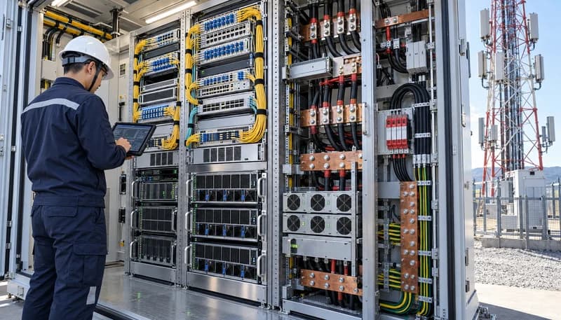
1. The AI-RAN Paradigm Shift: Architectural Divergence Between Fixed-Function ASICs and GPU-Driven Layer 1 PHY Compute
Traditional cellular baseband processing relies on custom Application-Specific Integrated Circuits (ASICs) and System-on-Chips (SoCs) engineered specifically for the deterministic mathematical pipelines of 3GPP Layer 1 (PHY). In conventional Baseband Units (BBUs), high-throughput, latency-critical operations—such as Low-Density Parity-Check (LDPC) channel coding, Fast Fourier Transforms (FFT/IFFT), and Massive MIMO digital beamforming weight calculations—are hardwired into silicon. This design delivers exceptional electrical efficiency, typically constraining total baseband blade power consumption to 150W–300W per sector under full 100 MHz channel bandwidth. However, this fixed architecture limits field upgradability for evolving 5G-Advanced and emergent 6G physical layer waveforms, and prevents concurrent real-time machine learning execution at the radio edge.
The AI-RAN paradigm breaks this paradigm by virtualizing Layer 1 processing onto programmable, massively parallel Graphics Processing Units (GPUs) and integrated Data Processing Units (DPUs). By executing the physical layer through highly optimized CUDA/C++ kernels, operators gain the flexibility to dynamically allocate compute cycles between 3GPP radio frame processing and edge AI inferencing tasks—such as automated channel estimation, dynamic beam synthesis, and multi-access edge computing (MEC). Yet this flexibility introduces significant hardware-level challenges. GPU architectures rely on Single Instruction, Multiple Threads (SIMT), which exhibits higher base power dissipation, larger silicon die areas, and a thermal design power (TDP) per accelerator node ranging between 300W and 700W. Translating these processing engines into mission-critical telecom sites demands microsecond-level execution determinism to satisfy strict 3GPP Transmission Time Interval (TTI) deadlines, completely rethinking how cell site infrastructure handles compute density.
Enforce strict real-time OS scheduling (PREEMPT_RT / real-time Linux kernel) to bound GPU kernel launch jitter within sub-50µs execution envelopes.
Map 3GPP Release 18/19 5G-Advanced LDPC decoding and beamforming kernels to dedicated compute units, isolating non-deterministic third-party AI inference via hardware-enforced spatial partitioning.
Guarantee continuous sub-millisecond TTI scheduling (e.g., 250µs for 30 kHz subcarrier spacing) to prevent Hybrid Automatic Repeat Request (HARQ) buffer overflows and Layer 1 frame drops.
2. Macro Base Station Power Budget Expansion: Sizing -48V DC Rectifier Systems and High-Density Distribution Busbars
Standard outdoor macro base stations are traditionally designed around an operational electrical envelope of 1.5 kW to 3.5 kW per cabinet, providing sufficient direct current (-48V DC nominal) to feed traditional baseband shelves, microwave backhaul terminals, and masthead Remote Radio Units (RRUs). Introducing GPU-accelerated AI-RAN compute nodes doubles or triples the core cabinet consumption, pushing continuous thermal and electrical loads to 6.0 kW–12.0 kW per enclosure. Because telecommunications sites operate strictly on nominal -48V DC infrastructure (with float voltages maintained between 53.5V and 54.0V), this surge in real power corresponds to a dramatic rise in current draw. A multi-blade GPU-accelerated installation running at 9.6 kW demands 200A of continuous current at -48V, testing the thermal and ampacity limits of legacy DC distribution assemblies.
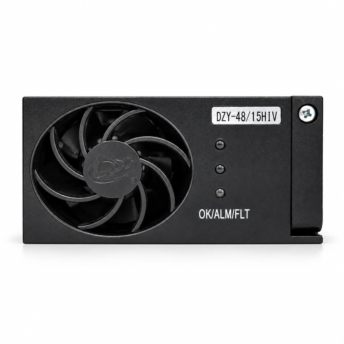
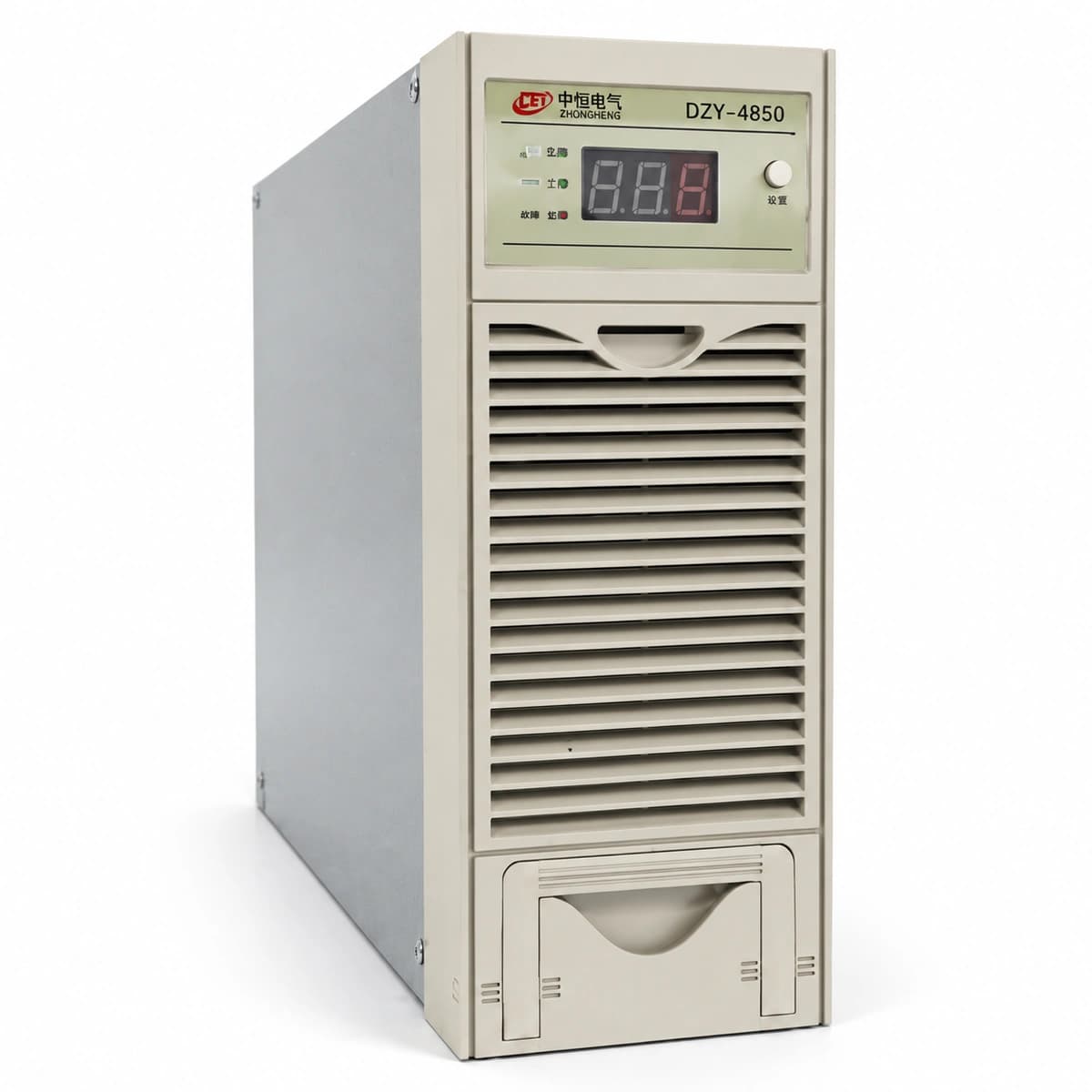
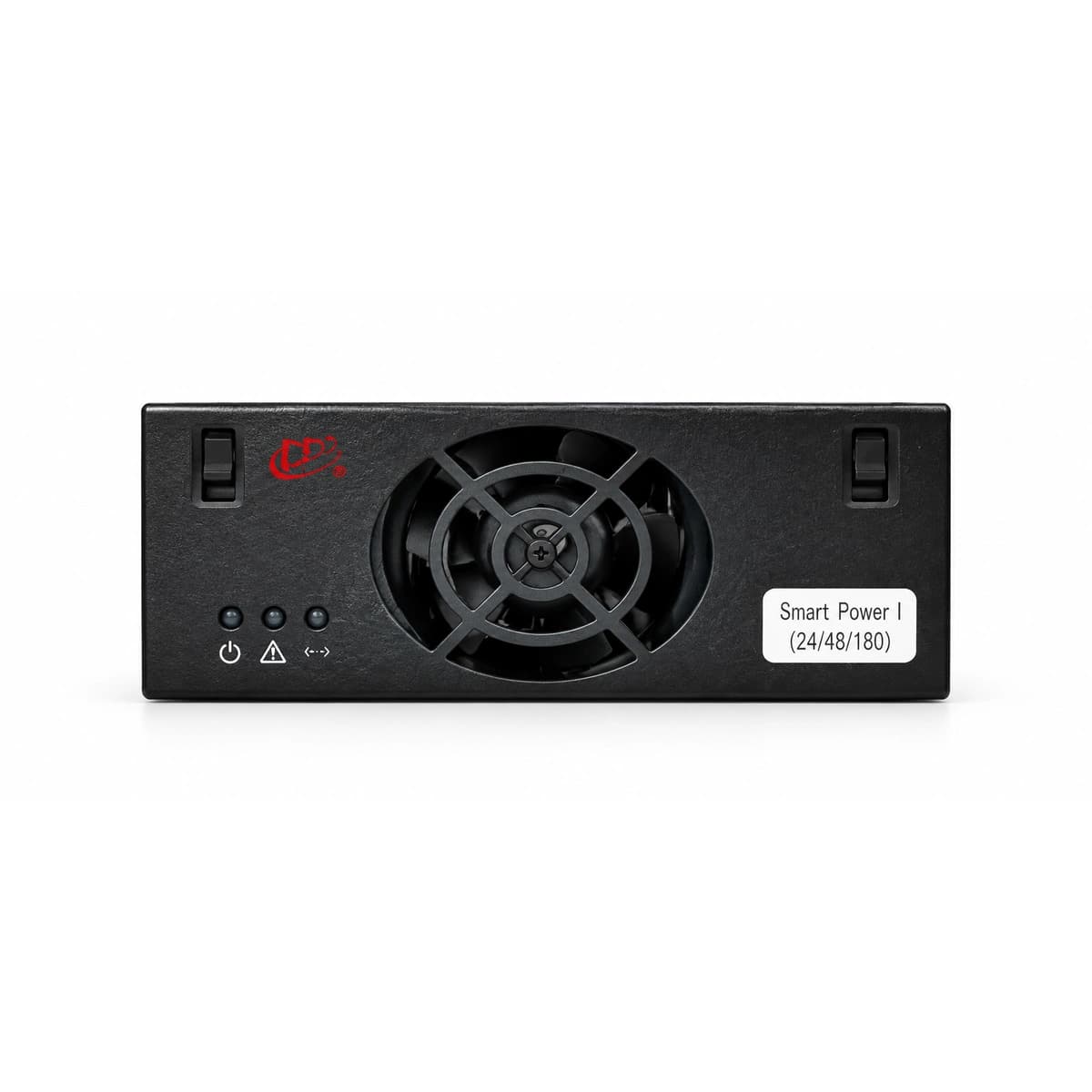
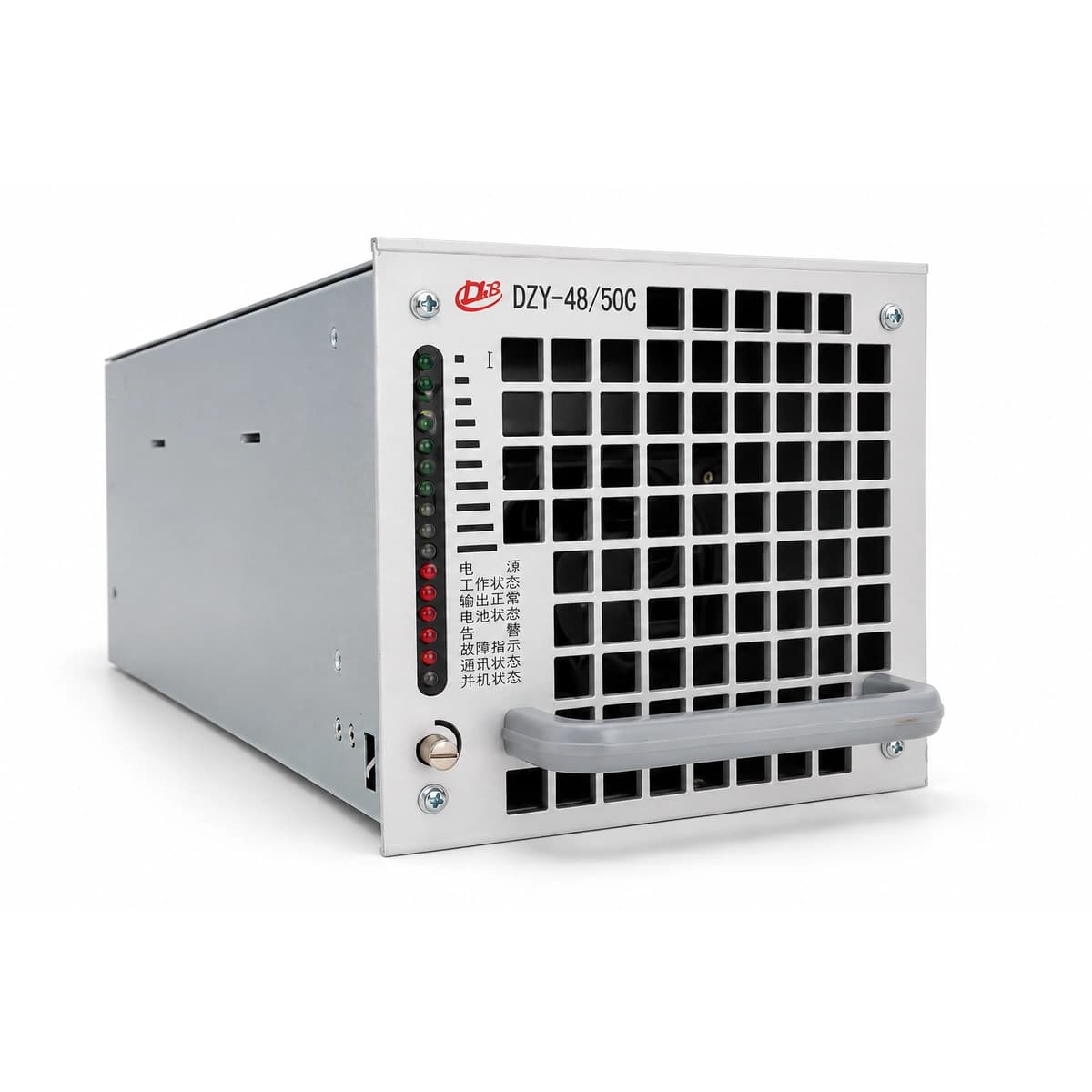
To prevent severe resistive voltage drops across cabinet distribution lines, brownfield power infrastructure must replace legacy 100A rectifier subracks with high-capacity 200A to 400A subracks populated with modular 3000W to 6000W switch-mode rectifier units. These rectifiers must deliver ultra-high conversion efficiencies (>96.5% to 98%) across a 30% to 90% load range to minimize parasitic cabinet heat dissipation. Concurrently, internal power distribution must be upgraded from standard wiring harnesses to low-impedance, electro-tin-plated solid copper busbars. Sizing busbar cross-sections must follow strict conservative current-density limits (typically <1.5 A/mm²) to ensure total cabinet distribution drop remains below 0.5V from the rectifier output terminals to the individual GPU blade input terminals, maintaining voltage integrity well above the low-voltage cutoff threshold of 42.0V.
Upgrade site rectifier bays to N+1 redundant architectures capable of supplying 200A–400A continuous DC current at nominal 53.5V–54.0V float levels.
Implement high-efficiency (>96% peak) switch-mode rectifier modules certified for Telcordia GR-3108-CORE Class 4 outdoor environments.
Size solid copper DC distribution busbars to maintain total internal cabinet resistive voltage drop below 500mV under maximum peak ampacity.
3. Dynamic Transients and Micro-Outage Buffering: High-Rate Lithium Iron Phosphate (LiFePO4) Battery and Supercapacitor Storage
Radio access networks operate under highly erratic, dynamic load profiles driven by real-time user traffic, Physical Resource Block (PRB) allocations, and Massive MIMO beamforming states. In a GPU-based Layer 1 environment, transitioning from an idle radio frame to a fully loaded cell across 64T64R antenna configurations causes near-instantaneous current steps. The GPU compute engine can swing its power consumption from 20% to 100% within a few milliseconds, imposing extreme current ramp rates (di/dt > 50A/ms) on the -48V DC rail. Traditional valve-regulated lead-acid (VRLA) batteries and first-generation lithium packs lack the internal impedance characteristics required to absorb these rapid current differentials, causing inductive rail voltage dips that can trigger under-voltage lockouts on onboard point-of-load (PoL) DC-DC converters.
To suppress these transient swings and protect site reliability, the DC energy storage subsystem requires high-rate Lithium Iron Phosphate (LiFePO4) battery modules capable of continuous 3C to 5C discharge bursts. These packs must be paired with low-Equivalent Series Resistance (ESR) electric double-layer capacitors (supercapacitors) or hybrid ultracapacitor banks connected in parallel with the main distribution bus. During severe grid micro-outages (<20ms) or rapid grid transfer events, the low-ESR capacitive layer handles the initial microsecond di/dt impulse, holding the DC bus voltage stable within the mandatory 46V to 55V operational window while the primary LiFePO4 chemistry assumes the full backup load, preserving 99.999% site availability without service interruption.
Deploy high-rate LiFePO4 battery modules supporting continuous 3C discharge rates and peak 5C dynamic step response.
Integrate distributed low-ESR supercapacitor modules along the -48V distribution rail to damp di/dt spikes exceeding 50A/ms.
Calibrate battery Low-Voltage Disconnect (LVD) contactors to 43.2V while ensuring dynamic transient dips never violate the 40.5V minimum operating threshold of GPU point-of-load converters.
4. Outdoor Thermal Management in Compact Enclosures: Vapor Chamber Heat Spreaders, IP55/IP65 Fan Aerodynamics, and Extreme Ambient Hardening
Unlike controlled hyperscale data centers with dedicated chillers and liquid cooling manifolds, outdoor telecommunications cabinets rely entirely on air-based or closed-loop air-to-air thermal exchange. These enclosures are regularly deployed in harsh environments characterized by solar radiation flux up to 1120 W/m² and ambient air temperatures ranging from -40°C to +55°C. Dissipating upwards of 700W from a dense, localized silicon package within a sealed, dust- and moisture-resistant IP55 or IP65 enclosure represents a significant thermal engineering challenge. Liquid cooling loops deployed to outdoor base stations introduce critical single-point failure vectors—such as mechanical pump failure, coolant freezing at sub-zero temperatures, and fluid leaks onto live -48V busbars—making robust, highly accelerated air cooling the preferred carrier-grade approach.
Achieving required heat flux transfer without liquid loops necessitates advanced phase-change thermal solutions. Base station server blades must integrate high-capacity 3D vapor chambers with sintered copper powder wicks, directly soldered to high-aspect-ratio, nickel-plated aluminum skived-fin heat sinks. These vapor chambers rapidly spread localized heat across the full width of the blade enclosure, preventing local die hot-spots. To push sufficient volumetric airflow through the high-impedance fin arrays, cabinet doors or subrack assemblies must incorporate high-static-pressure, pulse-width-modulated (PWM) dual-ball-bearing fan trays delivering between 300 and 600 cubic feet per minute (CFM). Dynamic acoustic management and variable-speed fan curve tracking ensure GPU die junction temperatures (Tj) remain strictly below 85°C, preserving component reliability even during peak desert summer ambient conditions.
Engineer 3D vapor chamber and composite heat-pipe baseplates capable of dissipating localized silicon heat flux exceeding 35 W/cm².
Utilize high-static-pressure, IP55/IP65-rated brushless DC fan arrays equipped with tachometer feedback and PWM speed regulation to drive 300–600 CFM across dense fin matrices.
Guarantee maximum silicon junction temperature (Tj) remains below 85°C under +55°C external ambient conditions with 1120 W/m² direct solar loading.
5. Optical Fronthaul and Deterministic Synchronization: eCPRI 25G/100G Interfaces, IEEE 1588v2 PTP Jitter Bounds, and Layer 1 Latency Compliance
The transmission architecture of an AI-RAN node centers on the optical fronthaul, which carries digitized RF I/Q time-domain or frequency-domain data between the GPU-accelerated baseband server and the distributed Remote Radio Units / Active Antenna Units (AAUs). This interface leverages the Enhanced Common Public Radio Interface (eCPRI) protocol running over high-speed 25Gbps (SFP28) or 100Gbps (QSFP28) optical transceivers. To bypass host CPU operating system bottlenecks and eliminate latency overheads, modern AI-RAN platforms implement GPUDirect RDMA (Remote Direct Memory Access). This pipeline routes eCPRI Ethernet packets straight from the network interface card or DPU into GPU High-Bandwidth Memory (HBM) over the PCIe bus, entirely bypassing system DRAM and keeping one-way host transport latency under 15 microseconds.
Phase, frequency, and time synchronization across the fronthaul must meet uncompromising precision standards. 5G Time Division Duplexing (TDD), coordinated multipoint (CoMP), and Massive MIMO inter-cell interference cancellation require end-to-end relative time alignment error (TAE) between antenna elements to remain well below 65 nanoseconds. Consequently, the GPU acceleration blade must incorporate hardware-based IEEE 1588v2 Precision Time Protocol (PTP) Telecom Profile (ITU-T G.8275.1) processing. The internal compute platform must feature a dedicated Telecom Boundary Clock (T-BC) or Telecom Time Slave Clock (T-TSC) conforming to Class C (max time error ≤ 10ns) or Class D specifications. Strict hardware packet time-stamping at the physical optical layer isolates the radio pipeline from software interrupts and PCIe scheduling jitter, preserving absolute temporal determinism across the cellular interface.
Deploy 25G/100G eCPRI interfaces using industrial-grade (-40°C to +85°C) SFP28/QSFP28 optical transceivers with real-time digital diagnostic monitoring.
Enforce ITU-T G.8275.1 telecom profile synchronization utilizing Class C hardware timestamping engines with absolute time error budget bounded within <10ns.
Configure GPUDirect RDMA pipelines to transfer Layer 1 I/Q bitstreams directly into GPU memory with sub-15µs total host interface latency.
6. Brownfield Cell Site Modernization Playbook: Step-by-Step Retrofit, DC PDU Breaker Coordination, and Field Commissioning Standards
Upgrading an operational brownfield cell site to support AI-RAN infrastructure requires an exact, non-disruptive modernization process that preserves ongoing 4G/5G carrier services. The process begins with an audit of the existing utility AC service feed, alternating current distribution panel (ACDP), and DC Power Distribution Unit (PDU). Before mounting high-draw compute hardware, technicians must inspect and upgrade main AC-to-DC breaker ratings, install expanded rectifier bays, and confirm battery string health through online conductance tests. Live hot-cutover procedures demand parallel installation of temporary DC power feeds to isolate mission-critical radio carriers while primary cabinet busbars are replaced or reinforced with higher-ampacity copper bars.
A critical engineering requirement during brownfield retrofitting is DC circuit breaker selectivity and protection coordination. Legacy 30A to 50A branch breakers are insufficient for high-density compute shelves; field engineers must integrate heavy-duty, magnetic-hydraulic DC circuit breakers rated between 150A and 400A with an interrupt capacity (IC) of at least 10kA at -48V DC. The trip curves of these breakers must coordinate precisely with upstream main battery disconnects and downstream server point-of-load protection, preventing upstream cascade trips during an isolated short-circuit within a GPU blade. Commissioning protocols conclude with comprehensive field validation: performing full-load thermal imaging scans under maximum simulated PRB traffic, verifying 1PPS (Pulse Per Second) phase alignment on an oscilloscope, and capturing DC ripple levels (<100mV peak-to-peak) to guarantee robust carrier-grade operation.
Field engineers must adhere to strict commissioning sequences to confirm hardware integrity before commercial traffic cutover. Verification requires measuring the loop resistance of new 2/0 AWG or 4/0 AWG DC feeder runs to ensure that line drop remains strictly beneath engineered targets at maximum draw. Once power stability is confirmed, the synchronization pipeline must undergo a continuous 24-hour stress test, monitoring for PTP packet delay variation (PDV) and loss-of-lock events. Finally, failover testing must validate that loss of one rectifier phase or a simulated single-fan failure triggers predictable, graceful performance throttling rather than an uncoordinated baseband system crash.
Coordinate magnetic-hydraulic DC breakers (150A–400A, 10kA IC) to guarantee selective clearing between individual GPU blades and main cabinet DC feeds.
Run double 2/0 AWG or 4/0 AWG low-smoke zero-halogen (LSZH) copper cables to limit continuous DC voltage drop to <1.0V between battery terminals and compute racks.
Execute formal commissioning sign-off: verify DC bus ripple remains below 100mV peak-to-peak and validate 1PPS phase alignment with <10ns time variance under 100% compute load.
Engineering Procurement & Technical Desk
For technical datasheets, custom power topology design, or volume export quotations, reach out to HEFENGQI engineers.