The Physics of Infrasound (<20 Hz) and Long-Wavelength Propagation
Infrasound encompasses acoustic energy propagating at frequencies below the nominal human auditory threshold of 20 Hz, corresponding to atmospheric acoustic wavelengths ranging from 17.15 meters at 20 Hz to 171.5 meters at 2 Hz in standard ambient air (speed of sound c = 343 m/s). At these physical dimensions, sound waves cease to interact with architectural envelopes as geometric rays; instead, they function as non-diffractive pressure waves that bend smoothly around physical perimeter barriers and diffract past geographic obstructions without significant shadow-zone attenuation. Furthermore, classical atmospheric absorption governed by molecular relaxation (ISO 9613-1) yields virtually zero attenuation (<0.01 dB/km at 10 Hz) compared to high frequencies, allowing low-frequency waves to propagate kilometers across residential zones virtually unattenuated.
Atmospheric boundary layer phenomena, particularly nocturnal radiative temperature inversions and low-level wind shear gradients, create severe acoustic ducting that refracts infrasonic wavefronts downward toward the ground plane. Standard environmental noise assessments rely on the A-weighting network (dBA), which applies an aggressive filter (-50.5 dB attenuation at 20 Hz and -70.4 dB at 10 Hz) based on the equal-loudness contours of human hearing at moderate volumes. This renders dBA metrics mechanically blind to infrasound energy that induces whole-body somatosensory excitation (thoracic and abdominal wall resonance occurring between 4 Hz and 8 Hz) and triggers secondary structural rattle in nearby residential light-frame building elements such as windows, doors, and drywall partitions.
Eliminate dBA metrics as the sole compliance index; implement flat (Z-weighting) and infrasound-specific (G-weighting) continuous spectral logging across the 1 Hz to 100 Hz frequency domain.
Model environmental propagation using parabolic equation (PE) and wave-based boundary element methods (BEM) accounting for nocturnal temperature inversions and wind refraction profiles.
Calculate structural rattle thresholds for neighboring buildings by benchmarking interior room unweighted low-frequency pressure against ANSI S12.9 Part 4 / Annex D criteria.
Cooling Plant Fluid Aerodynamics: Large Axial Fans & Blade Pass Frequency (BPF)
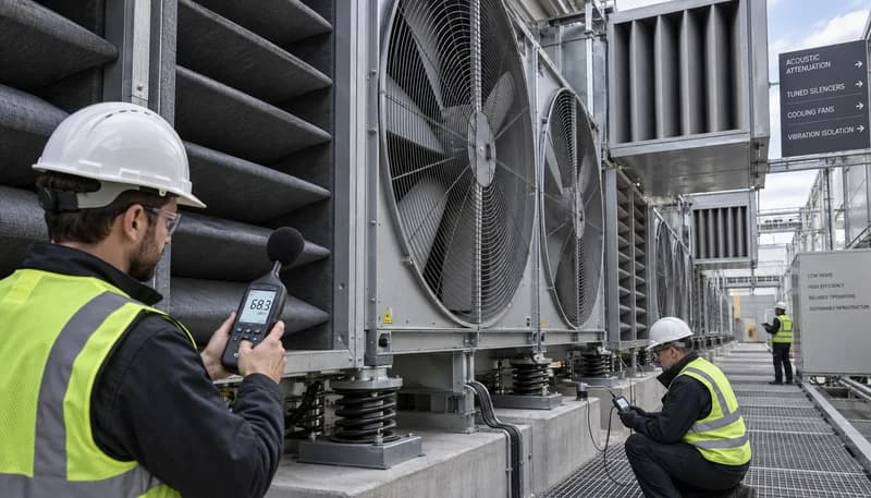
Mechanical heat rejection equipment—such as induced-draft cooling towers, closed-circuit fluid coolers, and dry cooler condenser banks—represents the primary airborne source of continuous low-frequency tonal energy in hyperscale campuses. The fundamental acoustic generator is periodic aerodynamic loading as each blade traverses localized spatial distortions in the inlet velocity profile, yielding a discrete Blade Pass Frequency: BPF = (N_blades × RPM) / 60. For standard 12-blade, 2.4-meter axial cooling tower fans operating at 300 to 450 RPM, the resulting fundamental BPF falls between 60 Hz and 90 Hz, but sub-harmonic aerodynamic interactions and non-uniform turbulence intake generate large-scale vortex shedding across the 5 Hz to 25 Hz infrasonic regime.
Acoustic dipole radiation strength scales directly with the sixth power of tip speed (W_acoustic ∝ U_tip^6), whereas mass airflow scales linearly with rotational speed. When high-solidity fan blades operate under high static backpressures, boundary layer separation occurs over the suction surface, shedding turbulent wake vortices whose Strouhal shedding frequencies (St = f × L / U) fall into the infrasound spectrum. At our infrastructure engineering research institute, computational aeroacoustic (CAA) modeling demonstrates that shifting from multi-blade high-RPM configurations to high-efficiency, aerodynamically cambered, large-diameter fans running at lower tip speeds drastically dampens broad-spectrum aerodynamic vortex shedding while relocating tonal BPF content away from structural coincidence bands.
Specify large-diameter electronically commutated (EC) axial fans engineered to maintain blade tip speeds below 35 m/s under peak thermal design loads.
Integrate bell-mouth aerodynamically contoured inlet cowlings and upstream flow-straightening stators to eliminate non-uniform ingestion turbulence that drives low-frequency dipole acoustic generation.
Stagger rotational velocities across adjacent modular dry cooler bays by 5% to 8% to prevent phase synchronization and coherent tonal amplification at shared Blade Pass Frequencies.
Diesel Genset Exhaust & Mechanical Reciprocating Resonance
Hyperscale backup generation relies on multi-megawatt reciprocating diesel engines (typically 2.5 MW to 3.5 MW, 16- or 20-cylinder configurations running at 1500 or 1800 RPM). During routine monthly maintenance load-banking or grid failure events, these engines become potent infrasound emitters. The gas exchange process injects massive discrete pressure pulses into the exhaust manifold at the cylinder firing frequency: f_firing = (Cylinders × RPM) / (120) for four-stroke cycles. For a 16-cylinder engine running at 1800 RPM, this fundamental firing pulse sits at 240 Hz, but cylinder-to-cylinder combustion variance, turbocharger surging, and secondary exhaust valve timings excite powerful low-frequency sub-harmonics within the 4 Hz to 16 Hz envelope.
Standard dissipative industrial silencers (packed with mineral wool or fiberglass) exhibit near-zero acoustic insertion loss below 63 Hz because the physical acoustic wavelength vastly exceeds the silencer pack thickness. When acoustic waves travel down long exhaust stacks, impedance discontinuities establish acoustic standing waves governed by open-closed organ pipe resonance: f_n = (2n - 1)c / (4L). If a stack resonance frequency coincides with an engine firing sub-harmonic, acoustic amplification of 15 dB to 25 dB occurs. Mitigation requires reactive acoustic attenuation—specifically multi-chamber volume resonators and tuned side-branch Helmholtz resonators—paired with peak-shaving Battery Energy Storage Systems (BESS) that eliminate engine cycling during uncritical dispatch windows.
Size reactive exhaust silencers with tuned internal Helmholtz expansion chambers and quarter-wave stub geometries engineered specifically to suppress sub-30 Hz stack resonances.
Design exhaust stack discharge geometries and lengths (L) to place longitudinal acoustic standing wave modes outside the operational reciprocating harmonic frequencies of the engine.
Deploy utility-scale lithium-ion or sodium-ion BESS architectures to absorb transient campus bridging loads and compress mandatory continuous diesel testing cycles to daytime operational windows.
Structural Vibro-Acoustics & Ground-Borne Transmission
Infrasonic perception frequently manifests through structure-borne vibro-acoustic energy rather than airborne propagation. Massive rotating mechanical plant equipment—including primary chilled water centrifugal chillers, industrial cooling towers, and diesel engine blocks—transmits dynamic cyclic shear and compression forces directly into elevated concrete structural slabs or grade-level foundation pads. This mechanical excitation travels through solid structural media as longitudinal, flexural, and ground-borne Rayleigh waves. Rayleigh waves exhibit minimal geometric damping (decaying proportionally to 1/√r, compared to 1/r^2 for spherical acoustic radiation in air), allowing mechanical vibration to traverse hundreds of meters of soil stratigraphy into surrounding building basements.
Vibro-acoustic coupling occurs when mechanical excitation frequencies match the natural flexural resonance modes of concrete elevated floor slabs or structural framing (typically 6 Hz to 14 Hz). If equipment is improperly isolated, the foundation acts as a gigantic mechanical diaphragm, radiating acoustic infrasound straight into the air. Vibration isolation systems must be modeled using transmissibility theory: T = √[(1 + (2ζr)^2) / ((1 - r^2)^2 + (2ζr)^2)], where r = f_operating / f_natural. To ensure an isolation efficiency exceeding 95% at 10 Hz, the mounted system natural frequency (f_n) must be tuned below 2.5 Hz, necessitating specialized structural dynamics engineering.
Install multi-directional unhoused coiled steel spring isolators featuring integrated viscous dampers with static deflections exceeding 50 mm to achieve system natural frequencies below 2.2 Hz.
Pour reinforced concrete inertia bases with an equipment-to-base mass ratio of at least 2:1 to 3:1 directly beneath all primary dynamic cooling plant pumps, chillers, and compressors.
Execute dynamic finite element analysis (FEA) of elevated mechanical penthouses and plant slabs to ensure structural natural frequencies maintain a minimum 30% separation from mechanical forcing frequencies.
Liquid Cooling Transformation & Hydronic Noise Reduction
The hyperscale transition to Direct-to-Chip (D2C) liquid cooling, single-phase immersion tanks, and Rear-Door Heat Exchangers (RDHx) fundamentally transforms the acoustic profile of data halls. By routing thermal energy directly through high heat-capacity dielectric fluids or treated water-glycol loops, volumetric air transport demands drop by 70% to 90%. This enables data center operators to eliminate dense arrays of high-RPM, 40 mm and 60 mm dual-rotor server chassis fans (which collectively generate high-frequency whine and aggregated low-frequency fluid turbulence) and significantly reduce the duty cycle of hyperscale computer room air handler (CRAH) fan matrices.
However, transitioning heat rejection to hydronics relocates the vibro-acoustic baseline to centralized Coolant Distribution Units (CDUs) and secondary fluid loops. Multi-stage variable-speed centrifugal pumps generate distinct Blade Pass Frequencies in fluid: f_bpf = (RPM × Impleller_Vanes) / 60, alongside fluid cavitation pulses and pressure ripple dynamics. If hydronic piping is rigidly anchored to structural steel or exterior facades, fluid pressure pulsations transfer directly into structural members. Robust hydronic acoustics requires low fluid flow velocities (<1.5 m/s in primary headers), non-wetting elastomeric expansion joints, and mass-loaded pipe clamping systems to decouple fluid infrasound from the architectural shell.
Design all secondary and tertiary hydronic distribution piping to limit maximum fluid velocity to 1.2 m/s - 1.5 m/s, suppressing turbulence-induced wall pressure fluctuations.
Install twin-sphere elastomeric flexible pipe connectors and stainless steel braided bellows immediately upstream and downstream of all Coolant Distribution Units (CDUs) and pump manifolds.
Isolate all hydronic pipe hangers from structural steel using dual-deflection neoprene-in-shear and spring elements rated for target pump operating frequencies down to 4 Hz.
Engineering Blueprint for Community Infrasound Compliance
Establishing verifiable compliance with municipal authorities and neighboring communities requires transitioning from legacy dBA metrics to standardized infrasound measurement protocols. The internationally accepted benchmark is ISO 7196, which specifies the G-weighting filter curve. The G-weighting network targets human perception of infrasound, possessing a sharp peak response centered between 10 Hz and 20 Hz (with a steep roll-off of 12 dB per octave above 20 Hz and below 10 Hz), establishing an operational reference threshold of 85 dB(G) where sub-audible pressure fluctuations become perceptible to the human nervous and vestibular systems.
Precise field quantification requires engineering instrumentation capable of handling sub-audible pressures without wind contamination. Standard acoustic measurement systems suffer from high self-noise and convective wind turbulence across microphones below 20 Hz. Research methodologies executed by RICEWIND mandate the deployment of Class 1 low-frequency condenser microphones or microbarometers with specialized pressure-equalized preamplifiers flat down to 0.1 Hz, shielded by multi-arm porous micro-hose wind noise attenuation arrays. Perimeter acoustic treatments should incorporate cantilevered, composite micro-perforated sound barrier walls engineered with acoustic mass surfaces of at least 35 kg/m^2 to damp low-frequency transmission loss performance down to the lowest mechanical harmonics.
Deploy perimeter infrasound monitoring stations utilizing low-noise 1/2-inch or 1-inch pressure-field microphones linear down to 0.5 Hz, enclosed in multi-port micro-porous hose arrays.
Incorporate ISO 7196 dB(G) and ANSI S12.9 Part 4 / Annex D low-frequency criteria into all project Environmental Impact Assessments (EIAs) and continuous fence-line monitoring networks.
Construct perimeter acoustic barriers with minimum surface densities of 35 kg/m^2, utilizing low-frequency tuned micro-perforated sound absorber panels to mitigate boundary diffraction.
Engineering Procurement & Technical Desk
For technical datasheets, custom power topology design, or volume export quotations, reach out to HEFENGQI engineers.