ZTE / DC power systems

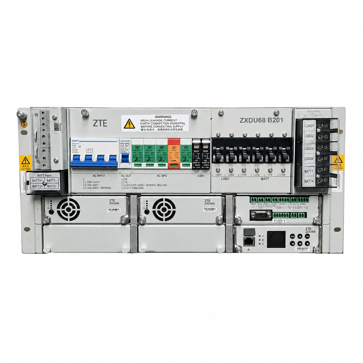
ZXDU68 B201 Equipment information & support

The ZXDU68 S501 is an integrated rack-mounted -48V DC indoor power system incorporating AC/DC distribution, intelligent monitoring, and high-efficiency 50A rectifiers up to 300A capacity.

Equipment information

Brand
ZTE
Equipment model
ZXDU68 B201
Equipment type
DC power systems
Controller / software version
Confirm against the installed equipment
View full product specifications
ZXDU68 B201 Official Product View 1

Information below comes from the current product catalogue. Confirm the controller, software version and configuration of the installed equipment separately.

Output Voltage Range
-42 to -58 VDC
Output Voltage Range
-42 ~ -58 VDC
AC Input Voltage
80 - 300 VAC
AC Input Voltage Range
80 ~ 300 VAC
Grid Frequency Range
45 - 66 Hz
Input Grid Type
Three-phase 380V / Single-phase 220V

Alarms & troubleshooting

AC_FAIL (AC Mains Failure / Phase Loss)
CSU Alarm LED Red solid, Rectifier Run LED Off, Rectifier Alarm LED Amber/Red solid
Grid blackout, upstream AC breaker trip, AC input voltage below low-voltage threshold, or open-circuit on an AC phase
1. Measure voltage at AC input terminals (L1/L2/L3/N) using a digital multimeter to confirm grid status. 2. Inspect cabinet AC input circuit breakers and SPD backup breakers for trips. 3. Check SPD status window; replace module if red indicator is visible. 4. If grid voltage is normal but phase loss persists, verify and torque loose wiring at the AC terminal block.
RECT_HVSD (Rectifier Output Overvoltage Shutdown)
Faulty Rectifier ALM LED Red solid, RUN LED Off, CSU displays hardware lockout state
Internal voltage control feedback loop failure, DC voltage sampling drift, or power MOSFET breakdown causing DC bus voltage to exceed hardware safety limit (59.5V)
1. Identify the alarmed rectifier slot ID via the CSU alarm log. 2. Unseat the faulty module and inspect backplane blind-mate connectors for bent pins, burn marks, or debris. 3. Reinsert module or power-cycle module AC feed, waiting 2 minutes for capacitor discharge to reset the latch. 4. If the overvoltage lockout reoccurs immediately upon restart, replace the rectifier module.
LLVD_ACT (Load Low Voltage Disconnect)
CSU Alarm LED Red solid, LLVD DC contactor auxiliary contacts open, non-critical branch power loss
Extended AC outage leading to deep battery discharge below the LLVD threshold (e.g. 44.0V), de-energizing the DC contactor to protect priority services
1. Verify site AC status and immediately start an emergency portable generator (DG). 2. Check individual battery cell and string bus voltages to prevent permanent battery sulfation. 3. Once AC is restored, verify rectifiers recharge the bus and confirm contactor re-closes automatically at reset voltage (e.g., 48.0V). 4. In extreme emergencies, use the CSU manual override switch to force contactor closure.
CAN_COMM_FAIL (Rectifier CAN Bus Communication Failure)
Rectifier ALM LED Amber blinking (0.5Hz), CSU interface displays module as Offline with communication loss alert
Backplane CAN ribbon cable loose, missing bus termination resistor (120 Ohm), damaged slot address pins, or transceiver failure causing polling timeout
1. Reseat the alarmed rectifier module, ensuring it is fully inserted and the latching mechanism is securely engaged. 2. Inspect internal CAN communication cables connecting the CSU controller to the backplane. 3. Measure unpowered resistance across CAN_H and CAN_L lines; it should read approximately 60 Ohms (parallel termination). 4. Swap the affected module into a different slot to determine whether the issue is isolated to the backplane slot or the module's CAN transceiver.
FAN_FAIL (Rectifier Fan Fault / Stalled Rotor)
Rectifier ALM LED blinking Amber/Red, module derating output to 50% or entering thermal protection shutdown
Air inlet blocked by debris/dust mats, fan bearing seizure, disconnected tachometer feedback line, or internal fan drive circuit failure
1. Withdraw the rectifier module and visually inspect the front dust filter and rear exhaust grill for debris or heavy dust accumulation. 2. Manually spin the fan blades to check for mechanical binding or bearing resistance. 3. Clean the fan assembly and heatsinks with dry compressed air, reinsert module, and observe initial fan spin-up test. 4. If the fan fails to rotate or reports abnormal RPM, replace the hot-swappable fan assembly or submit the module for repair.

Access Complete Maintenance & Full Alarm Troubleshooting Manual

This page lists high-frequency critical alarm codes commonly encountered in field maintenance. Comprehensive manufacturer troubleshooting matrices, board-level repair guides, detailed electrical schematics, and firmware commissioning manuals are delivered alongside equipment upon formal project procurement, accompanied by dedicated FAE technical support.

Share on-site information

  1. 01

    Identify the exact model

    Record the nameplate, system model and controller or module model.

  2. 02

    Keep the alarm details

    Record the full alarm text, indicator colour, timing and whether it persists.

  3. 03

    Describe recent changes

    Note recent replacements, software updates or configuration changes.

Record information visible in the existing interface. Electrical measurements, disassembly and replacement should follow the applicable manufacturer's manual and be performed by qualified personnel.

Your model and these details will be added to the enquiry form for you to review before sending.

Related technical articles

Browse the technical guides or send a question about this model.

View all articles

Need a replacement module or supporting equipment?

Confirm the full model, system configuration and compatibility requirements before enquiring about suitable products.

Ask about suitable products

Have a model and an on-site issue?

Share the exact model, alarm text and observed symptoms to help identify relevant information and compatibility requirements.

Request technical support