ZTE / Outdoor power systems

ZXDU58 W121 Equipment information & support

ZTE ZXDU58 W121 is a 3U rackmount DC power subrack delivering 120A with integrated AC distribution, battery LVD disconnect, and digital supervision.

Equipment information

Brand
ZTE
Equipment model
ZXDU58 W121
Equipment type
Outdoor power systems
Controller / software version
Confirm against the installed equipment
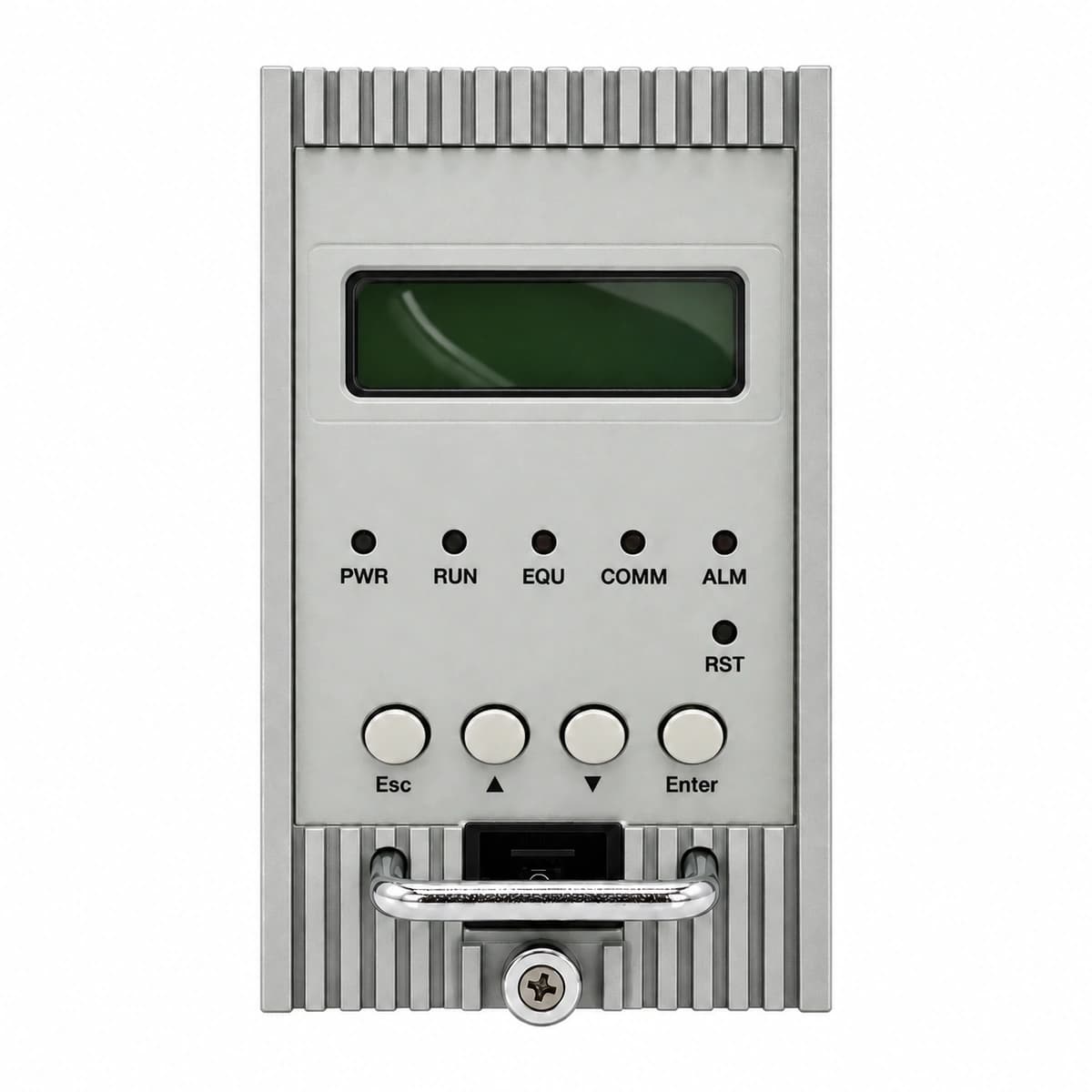
View full product specifications
ZXDU58 W121 Official Product View 1

Information below comes from the current product catalogue. Confirm the controller, software version and configuration of the installed equipment separately.

AC Input Voltage Range
85VAC ~ 290VAC VAC
Nominal DC Output Voltage
-48 V DC
Rectifier Module Slots
4 × ZXD1500 / 3 × ZXD2400 Slots
Physical Dimensions Spec
132 (3U) × 482 × 360 mm
System Monitoring Controller
CSU series intelligent monitoring controller

Alarms & troubleshooting

AC_FAIL (AC Mains Failure)
CSU/Rectifier ALM LED solid red, RUN LED off
External grid blackout, AC input circuit breaker tripped, phase loss, or input voltage out of operating range (<80 VAC or >300 VAC)
1. Verify whether the outdoor cabinet AC distribution switch and main input breaker are closed. 2. Measure the L-N / L-L input voltage with a multimeter to verify grid recovery. 3. If the breaker tripped on live mains, inspect the upstream SPD and wiring for short circuits before resetting.
DC_LOW_VOLT (DC Undervoltage / LLVD Disconnect)
CSU ALM LED flashing red (2Hz), audible buzzer on, LLVD contactor status indicates open
Prolonged AC power outage leading to battery depletion below threshold (default 45.0V), triggering Load Low Voltage Disconnect (LLVD)
1. Deploy a mobile diesel generator to the emergency AC inlet to restore power immediately. 2. Check the DC bus voltage and Battery State of Charge (SOC) on the CSU display. 3. Once AC is restored, verify rectifiers enter boost charging and confirm the LLVD contactor automatically reconnects.
REC_HVSD (Rectifier Output Overvoltage Hardware Shutdown)
Faulty rectifier module ALM/FAULT LED solid red, RUN LED off, CSU reports rectifier fault
Internal voltage control circuit failure causing rectifier DC output to exceed threshold (>59.5V), activating hardware lockout
1. Identify the slot ID of the locked rectifier module via the CSU display menu. 2. Pull out the faulty module, wait 1 minute for DC bus capacitors to discharge, and re-insert. 3. If the module trips into HVSD immediately again, declare hardware failure and replace with a spare rectifier.
BATT_TEMP_HIGH (Battery Over-Temperature Alarm)
CSU ALM LED amber/red solid, outdoor cabinet TEC cooler or fan operates at 100% capacity
Outdoor cabinet TEC/fan clogged with dust, thermal management circuit tripped, battery thermal runaway, or faulty NTC temperature sensor
1. Inspect the outdoor cabinet air intakes/exhausts for debris, clean air filters, and ensure cooling fans/TEC run smoothly. 2. Use an infrared thermometer to measure actual cell surface temperatures to rule out thermal runaway. 3. If physical temperatures are normal, check the NTC sensor resistance; replace the sensor if open-circuit or drifting.
SPD_FAULT (AC Surge Protective Device Failure)
AC SPD physical indicator window turns from green to red, CSU reports dry contact SPD alarm
AC mains experienced lightning strikes or high-energy surges, causing the Metal Oxide Varistor (MOV) to degrade and disconnect via thermal fuse
1. Inspect the AC distribution SPD cartridges to locate which phase or neutral module window shows red. 2. Disconnect the SPD backup circuit breaker (if equipped) and pull out the degraded cartridge. 3. Replace it with a new matching rating cartridge (e.g., 20kA/40kA), ensuring the indicator returns to green and the alarm clears.

Access Complete Maintenance & Full Alarm Troubleshooting Manual

This page lists high-frequency critical alarm codes commonly encountered in field maintenance. Comprehensive manufacturer troubleshooting matrices, board-level repair guides, detailed electrical schematics, and firmware commissioning manuals are delivered alongside equipment upon formal project procurement, accompanied by dedicated FAE technical support.

Share on-site information

  1. 01

    Identify the exact model

    Record the nameplate, system model and controller or module model.

  2. 02

    Keep the alarm details

    Record the full alarm text, indicator colour, timing and whether it persists.

  3. 03

    Describe recent changes

    Note recent replacements, software updates or configuration changes.

Record information visible in the existing interface. Electrical measurements, disassembly and replacement should follow the applicable manufacturer's manual and be performed by qualified personnel.

Your model and these details will be added to the enquiry form for you to review before sending.

Related technical articles

Browse the technical guides or send a question about this model.

View all articles

Need a replacement module or supporting equipment?

Confirm the full model, system configuration and compatibility requirements before enquiring about suitable products.

Ask about suitable products

Have a model and an on-site issue?

Share the exact model, alarm text and observed symptoms to help identify relevant information and compatibility requirements.

Request technical support