ZTE / Power management

ZXDU58 B900 Equipment information & support

The ZTE ZXDU58 B900 is an enterprise-grade -48V floor-standing indoor telecom DC power system engineered to deliver up to 900A of high-reliability output power with hot-pluggable high-efficiency rectifiers and intelligent dual-stage Low Voltage Disconnect (LLVD/BLVD) battery management.

Equipment information

Brand
ZTE
Equipment model
ZXDU58 B900
Equipment type
Power management
Controller / software version
Confirm against the installed equipment
View full product specifications
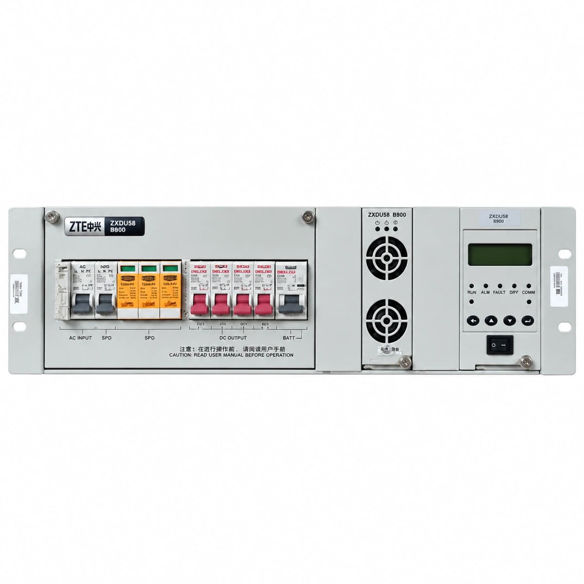
ZTE ZXDU58 B900 Official White Background Photo View 1

Information below comes from the current product catalogue. Confirm the controller, software version and configuration of the installed equipment separately.

AC Input Voltage Range
80VAC ~ 300VAC (3-Phase 5-Wire 380VAC) VAC
Smart Monitoring Controller
CSU500B / CSU401S Central Monitoring System
Cooling Method
Top exhaust fans and module smart thermal cooling
Nominal Output Voltage
-48VDC VDC
Rated Output Current
900A (Cabinet Capacity 52.2kW)
Managed Rectifier Capacity
Supports up to 18 × ZXD2400 / ZXD3000 Rectifiers

Alarms & troubleshooting

DC_VOLT_LOW
CSU Red Alarm LED solid ON, intermittent buzzer sounding
Extended AC mains failure causing battery discharge voltage to fall below the warning threshold (default -45.0VDC), or multiple rectifiers failed causing insufficient supply to meet load demand.
1. Immediately check main AC feed and emergency diesel generator status; 2. Inspect CSU module summary to identify failed rectifiers and reset tripped AC breakers; 3. Prepare portable generator or shed non-critical loads to prevent triggering LLVD/BLVD stage; 4. If AC is intact but rectifiers are offline, verify float charge parameters in the CSU.
AC_PHASE_FAIL
CSU Red Alarm LED blinking, system alarm relay energized
Loss of one or more phases in the incoming 3-phase AC grid, or one pole of the AC input circuit breaker is open/damaged, resulting in phase voltage <85VAC.
1. Use a True-RMS multimeter to measure L1-N, L2-N, L3-N and line-to-line voltages at AC input terminals; 2. Check upstream substation breakers and the AC surge protector (SPD) condition; 3. Inspect AC breaker contact integrity and terminal torque inside the cabinet for signs of thermal stress; 4. If phase failure persists, shed secondary loads to avoid continuous thermal stressing of rectifiers fed by remaining phases.
RECT_COMM_FAIL
Faulty rectifier yellow Comms LED blinking/OFF, CSU Yellow Alarm LED solid ON
CAN-bus communication interrupted between CSU and a specific rectifier; typically caused by loose ribbon cabling, bent/damaged backplane blind-mate pins, missing termination resistor, or failed module transceiver IC.
1. Withdraw the module and inspect rear blind-mate connectors for bent pins, physical damage, or debris; 2. Firmly reseat the module and lock the extraction handle, observing green and yellow self-test LED sequences; 3. Slot the module into an adjacent slot to isolate between module transceiver failure and backplane segment failure; 4. Execute a 'Re-address Rectifiers' command from the CSU maintenance interface.
BATT_TEMP_HIGH
CSU Yellow Alarm LED solid ON, display shows Battery Over-temperature
Battery surface or battery compartment ambient temperature exceeded warning threshold (typically set to 45°C–50°C); caused by HVAC failure, internal cell short-circuit leading to self-heating, or temperature probe drift.
1. Inspect battery room air conditioning and ventilation operation; 2. Scan the battery strings using an infrared thermographic camera to detect localized swelling or abnormal cell temperature rise; 3. Verify probe reading accuracy with a calibrated digital thermometer; replace the NTC probe if variance exceeds ±2°C; 4. If thermal runaway is suspected, immediately lower the float voltage setpoint or trip the associated battery circuit breaker.
SPD_FAULT
CSU Yellow Alarm LED solid ON, AC distribution SPD mechanical indicator turns from Green to Red
Surge Protective Device (SPD) in the AC distribution unit degraded or failed following high-energy lightning/transient surge, triggering its thermal disconnector, or the SPD auxiliary monitoring contact cable is detached.
1. Check the SPD status window in the AC distribution section to identify the tripped phase cartridge; 2. Switch off the dedicated SPD backup MCB, unplug the damaged varistor cartridge, and replace it with an identical OEM module (rated In 20kA / Imax 40kA); 3. Verify the integrity and resistance of the cabinet Protection Earth (PE) bonding conductor (target ≤5Ω); 4. Re-engage the SPD breaker and confirm on the CSU that the alarm has automatically cleared.

Access Complete Maintenance & Full Alarm Troubleshooting Manual

This page lists high-frequency critical alarm codes commonly encountered in field maintenance. Comprehensive manufacturer troubleshooting matrices, board-level repair guides, detailed electrical schematics, and firmware commissioning manuals are delivered alongside equipment upon formal project procurement, accompanied by dedicated FAE technical support.

Share on-site information

  1. 01

    Identify the exact model

    Record the nameplate, system model and controller or module model.

  2. 02

    Keep the alarm details

    Record the full alarm text, indicator colour, timing and whether it persists.

  3. 03

    Describe recent changes

    Note recent replacements, software updates or configuration changes.

Record information visible in the existing interface. Electrical measurements, disassembly and replacement should follow the applicable manufacturer's manual and be performed by qualified personnel.

Your model and these details will be added to the enquiry form for you to review before sending.

Related technical articles

Browse the technical guides or send a question about this model.

View all articles

Need a replacement module or supporting equipment?

Confirm the full model, system configuration and compatibility requirements before enquiring about suitable products.

Ask about suitable products

Have a model and an on-site issue?

Share the exact model, alarm text and observed symptoms to help identify relevant information and compatibility requirements.

Request technical support