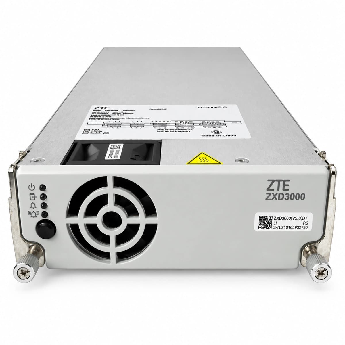
The ZXD3000 (V5.8) is a single-phase hot-swappable 3000W -48V DC high-efficiency switch-mode telecom rectifier designed for broad AC input conversions.
Information below comes from the current product catalogue. Confirm the controller, software version and configuration of the installed equipment separately.
AC grid outage, phase voltage below 80VAC or above 300VAC, input miniature circuit breaker (MCB) tripped, or loose terminal contact
1. Measure AC phase voltage at the backplane/input connector using a multimeter to verify voltage is within normal operational range (85VAC-295VAC); 2. Verify that the rectifier's dedicated AC input circuit breaker is closed; inspect for downstream shorts before resetting; 3. Reseat the rectifier firmly in its slot; if the fault persists despite valid AC input, replace the rectifier module.
DC_OVP_LOCK (DC Output Overvoltage Lockout)
IN LED solid green, OUT LED off, ALM LED solid red
Internal PWM loop regulation failure or optocoupler feedback breakdown, causing DC output to exceed hardware protection threshold (58.5V-60V) and triggering permanent shutdown lockout
1. Disconnect the rectifier from slot, wait 30 seconds for internal capacitors to discharge; 2. Reinsert to test if soft-start succeeds and output stabilizes at nominal 53.5V; 3. Measure DC bus voltage to ensure CSU (Central Supervision Unit) has not sent an erroneous float/boost voltage command; 4. If overvoltage trip recurs immediately, the internal secondary regulation circuit is damaged; replace the module.
IN LED solid green, ALM LED solid yellow (derating) or blinking yellow (thermal shutdown)
Ambient temperature exceeding 55°C, front air intake filter or ventilation ducts heavily clogged with dust, or insufficient airflow causing power heat sinks to overheat
1. Check air conditioning in the equipment room to bring ambient temperature back to standard operating range (<40°C); 2. Inspect and clear dust from front intake grilles and cabinet filter mesh; 3. Verify airflow at the rear exhaust to ensure cooling fan spins at full speed; 4. Allow heat sinks to cool down; the rectifier will automatically recover and clear the alarm once temperatures drop below threshold.
FAN_BLOCKED (Cooling Fan Fault / Speed Abnormal)
IN LED solid green, ALM LED flashing yellow or red (0.5Hz)
Foreign object jamming fan impeller, fan bearing seized due to wear, drive circuit open, or internal tachometer feedback wire disconnected
1. Visually inspect the front fan intake with a flashlight to verify no cable ties or debris block the impeller; 2. Power off the unit and gently spin blades using an insulated probe to feel for mechanical resistance; 3. If stiff or seized, remove front sub-cover and replace the 12V DC 4-wire PWM fan unit; 4. Power on and verify the fan runs through its POST self-test sequence and alarm LED turns off.
CAN_COMM_FAIL (CAN-bus Communication Failure / Imbalance)
IN LED solid green, OUT LED solid green, ALM LED slow blinking yellow (1Hz)
Gold finger connector pins on module backplane bent or oxidized breaking CANH/CANL differential pairs, CSU controller frozen, or internal CAN transceiver IC failure causing current-share loss
1. Check the CSU front screen to confirm whether the issue is isolated to a single rectifier or a system-wide CAN bus failure; 2. Withdraw the module and inspect the rear gold-finger connector pins for bending, corrosion, or contamination; clean with isopropyl alcohol; 3. Swap the module into an adjacent known-good slot to isolate backplane pin faults; 4. If the communication error persists in another slot, replace the rectifier module.
Access Complete Maintenance & Full Alarm Troubleshooting Manual
This page lists high-frequency critical alarm codes commonly encountered in field maintenance. Comprehensive manufacturer troubleshooting matrices, board-level repair guides, detailed electrical schematics, and firmware commissioning manuals are delivered alongside equipment upon formal project procurement, accompanied by dedicated FAE technical support.
Record the nameplate, system model and controller or module model.
02
Keep the alarm details
Record the full alarm text, indicator colour, timing and whether it persists.
03
Describe recent changes
Note recent replacements, software updates or configuration changes.
Record information visible in the existing interface. Electrical measurements, disassembly and replacement should follow the applicable manufacturer's manual and be performed by qualified personnel.
Related technical articles
Browse the technical guides or send a question about this model.