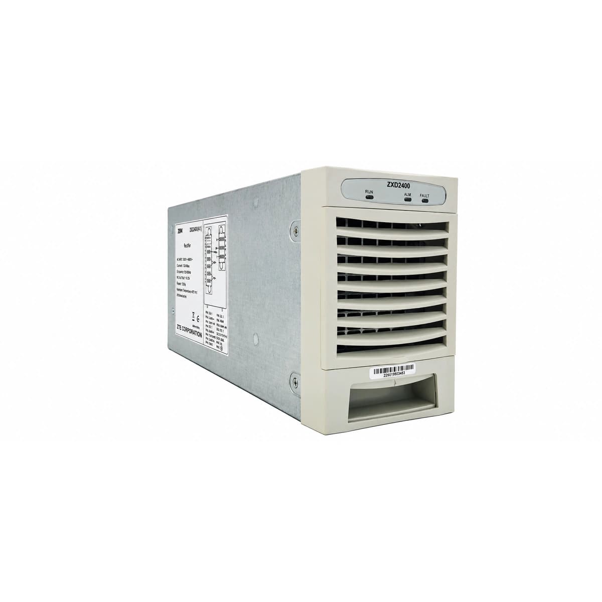
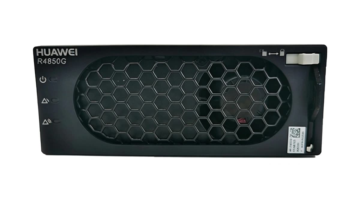
AC_IN_FAIL / AC_DERATE (AC Input Abnormal / Loss / Voltage Derating)
Power LED (Green) OFF or flashing; Protection LED (Yellow) steady ON; Fault LED (Red) OFF.
Utility grid blackout, phase loss, loose terminal screws, or AC input voltage out of operational window (<85VAC derating/cutoff, >295VAC OVP trip).
1. Measure L-N AC voltage at module slot with True-RMS multimeter;
2. Verify AC supply is within nominal range (85~295VAC);
3. Inspect upstream branch circuit breaker (MCB);
4. Retorque wiring terminals and verify neutral connection;
5. If voltage is nominal but yellow LED persists, reseat module and inspect connector pins; replace module if defective.
DC_OV_LOCKOUT / HVSD (DC Output Overvoltage Lockout / HVSD)
Power LED (Green) OFF; Fault LED (Red) steady ON (latched); Protection LED (Yellow) OFF.
Internal PWM loop failure, optocoupler feedback breakdown, or DC bus transient exceeding hardware HVSD threshold (~59.5VDC ±0.5V). Latches off to protect telecom equipment.
1. Extract faulted rectifier and trip its AC feed;
2. Wait at least 3 minutes to discharge internal bus capacitors;
3. Reseat module firmly and power up for a cold restart;
4. Check controller float/equalize target voltage settings (<58.5VDC);
5. If red LED immediately latches on restart, internal regulation failed; replace unit.
OTP_DERATE / OTP_SHUTDOWN (Over-Temperature Derating & Thermal Shutdown)
During derating: Green Power ON, Yellow Protection ON; Thermal shutdown: Green OFF, Yellow ON, Red Fault ON.
Ambient temperature exceeds 55°C, clogged dust filters, air recirculation, or heatsink thermistor (NTC) detecting internal power semiconductor temperature exceeding safety threshold (>105°C).
1. Check site air conditioning and ensure subrack intake air is <35°C;
2. Clean cabinet intake air filters;
3. Install blanking panels in unpopulated slots to eliminate hot air loops;
4. Allow module to cool and verify automatic recovery;
5. If ambient is cool and fan spins but alarm recurs, replace module.
COMM_FAIL / CAN_BUS_LOST (Rectifier CAN Bus Comm Lost / Offline)
Yellow Protection LED flashing (~1Hz); Green Power LED steady ON; Rectifier maintains default float voltage autonomously.
Loose CAN bus flat cable, dirty backplane connector pins, missing or damaged 120-ohm bus termination resistor, or slot address conflict.
1. Reseat module and confirm it latches completely into backplane;
2. Measure equivalent resistance across CAN_H and CAN_L (should read 55~65 ohms with two 120-ohm terminators in parallel);
3. Inspect communication ribbon cable between controller and subrack;
4. Run 'Module Rescan & Auto-Addressing' on controller LCD;
5. If only one slot fails, inspect backplane connector pins.