ZTE / DC power systems

ZXD1500 Equipment information & support

The ZTE ZXD1500 is a reliable switch-mode AC/DC telecom rectifier utilizing phase-shifted full-bridge topology and active PFC to supply clean -48V DC power with automated battery charging management.

Equipment information

Brand
ZTE
Equipment model
ZXD1500
Equipment type
DC power systems
Controller / software version
Confirm against the installed equipment
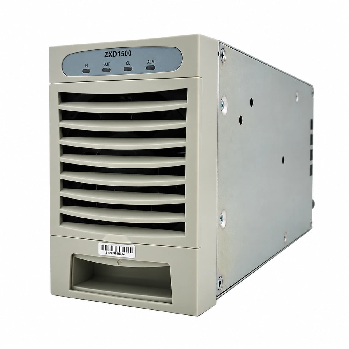
View full product specifications
ZXD1500 Official Product View 1

Information below comes from the current product catalogue. Confirm the controller, software version and configuration of the installed equipment separately.

Nominal DC Output Voltage
-48 V DC
Rated Output Current
30 A
Power Conversion Efficiency
95.0 %
Physical Dimensions Spec
132 × 85 × 287 mm
AC Input Voltage Range
85 ~ 300 V AC
Operating Temperature
-25 ~ +70 °C

Alarms & troubleshooting

AC_IN_FAIL (AC Input Voltage Fault/Failure)
RUN LED (Green) OFF, ALM LED (Yellow) Solid ON
Mains power blackout, AC input circuit breaker trip, or AC voltage out of operational range (<80VAC or >300VAC).
1. Measure AC input terminal voltage at the backplane using a multimeter to verify it is within range (85VAC–295VAC). 2. Inspect the sub-rack AC circuit breaker assigned to the rectifier; reset it if tripped after verifying no short circuit. 3. If input voltage is normal, re-seat the module to check connector pin contact; replace the rectifier module if fault persists.
OUT_OVP_LOCK (DC Output Overvoltage Hardware Lockout)
RUN LED (Green) OFF, FAULT LED (Red) Solid ON
Internal PWM loop regulation failure or secondary feedback loop breakdown causing DC bus voltage to exceed safety limit (>59.5VDC), triggering hardware lockout.
1. Unseat the module from the sub-rack and wait 3 minutes for high-voltage DC bus capacitors to fully discharge. 2. Re-insert the module; if the red FAULT LED latches on again, check the float/equalize voltage setpoints in the supervisory unit. 3. If system parameters are normal but the standalone module locks out immediately upon start, internal power components are damaged; replace the module.
MOD_OTP (Rectifier Module Over-Temperature Protection)
RUN LED (Green) Blinking, ALM LED (Yellow) Solid ON (RUN turns OFF if fully shut down)
Ambient temperature exceeds operating limits (>55°C), front air filter clogged, heavy dust accumulation on heatsinks, or ventilation channel obstructed.
1. Check equipment room air conditioning to restore ambient inlet temperature below 30°C. 2. Clean the sub-rack front dust filters and remove any obstructions blocking the rectifier's front intake or rear exhaust vents. 3. Allow the module heatsink to cool below internal auto-recovery threshold (typically <75°C heatsink sensor) and verify that output power auto-recovers.
FAN_FAIL (Cooling Fan Rotor Blocked/Speed Abnormality)
ALM LED (Yellow) Blinking, subsequently FAULT LED (Red) Solid ON
DC brushless cooling fan bearing seized, foreign object jamming fan blades, or tachometer (FG) sensor circuit disconnected.
1. Remove the module and perform visual inspection to ensure no foreign debris is jamming the blades; spin the fan manually to verify smooth rotation. 2. Verify that the fan wiring harness connector is firmly seated into the module control PCB header. 3. Power up again after debris clearance; if the fan fails to spin or the speed alarm persists, replace the internal fan sub-assembly.
COMM_FAIL (Communication Loss & Current Imbalance)
RUN LED (Green) Slow Flashing (0.5Hz), ALM LED (Yellow) Blinking
CAN/RS-485 bus open circuit between rectifier and Central Supervisory Unit (CSU), communication interface chip failure, or address ID collision preventing active current sharing.
1. Inspect the CSU display menu to verify module slot addressing configuration and eliminate address collisions. 2. Reseat the module firmly into its slot, ensuring backplane communication pins make solid contact without bent pins. 3. Execute a 'Bus Re-scan/Re-address' command via the CSU, or swap the module into a known-good slot to isolate whether the issue is the module's transceiver or the system backplane bus.

Access Complete Maintenance & Full Alarm Troubleshooting Manual

This page lists high-frequency critical alarm codes commonly encountered in field maintenance. Comprehensive manufacturer troubleshooting matrices, board-level repair guides, detailed electrical schematics, and firmware commissioning manuals are delivered alongside equipment upon formal project procurement, accompanied by dedicated FAE technical support.

Share on-site information

  1. 01

    Identify the exact model

    Record the nameplate, system model and controller or module model.

  2. 02

    Keep the alarm details

    Record the full alarm text, indicator colour, timing and whether it persists.

  3. 03

    Describe recent changes

    Note recent replacements, software updates or configuration changes.

Record information visible in the existing interface. Electrical measurements, disassembly and replacement should follow the applicable manufacturer's manual and be performed by qualified personnel.

Your model and these details will be added to the enquiry form for you to review before sending.

Related technical articles

Browse the technical guides or send a question about this model.

View all articles

Need a replacement module or supporting equipment?

Confirm the full model, system configuration and compatibility requirements before enquiring about suitable products.

Ask about suitable products

Have a model and an on-site issue?

Share the exact model, alarm text and observed symptoms to help identify relevant information and compatibility requirements.

Request technical support