ZTE / Optical communications and networking

ZTE 10G SFP+ 10km Equipment information & support

The ZTE 10G SFP+ 1310nm 10km (SM-10KM-1310-10G-C) is an enterprise-grade 10Gbps single-mode optical transceiver designed for long-distance 10G Ethernet connections up to 10 kilometers with duplex LC interface.

Equipment information

Brand
ZTE
Equipment model
ZTE 10G SFP+ 10km
Equipment type
Optical communications and networking
Controller / software version
Confirm against the installed equipment
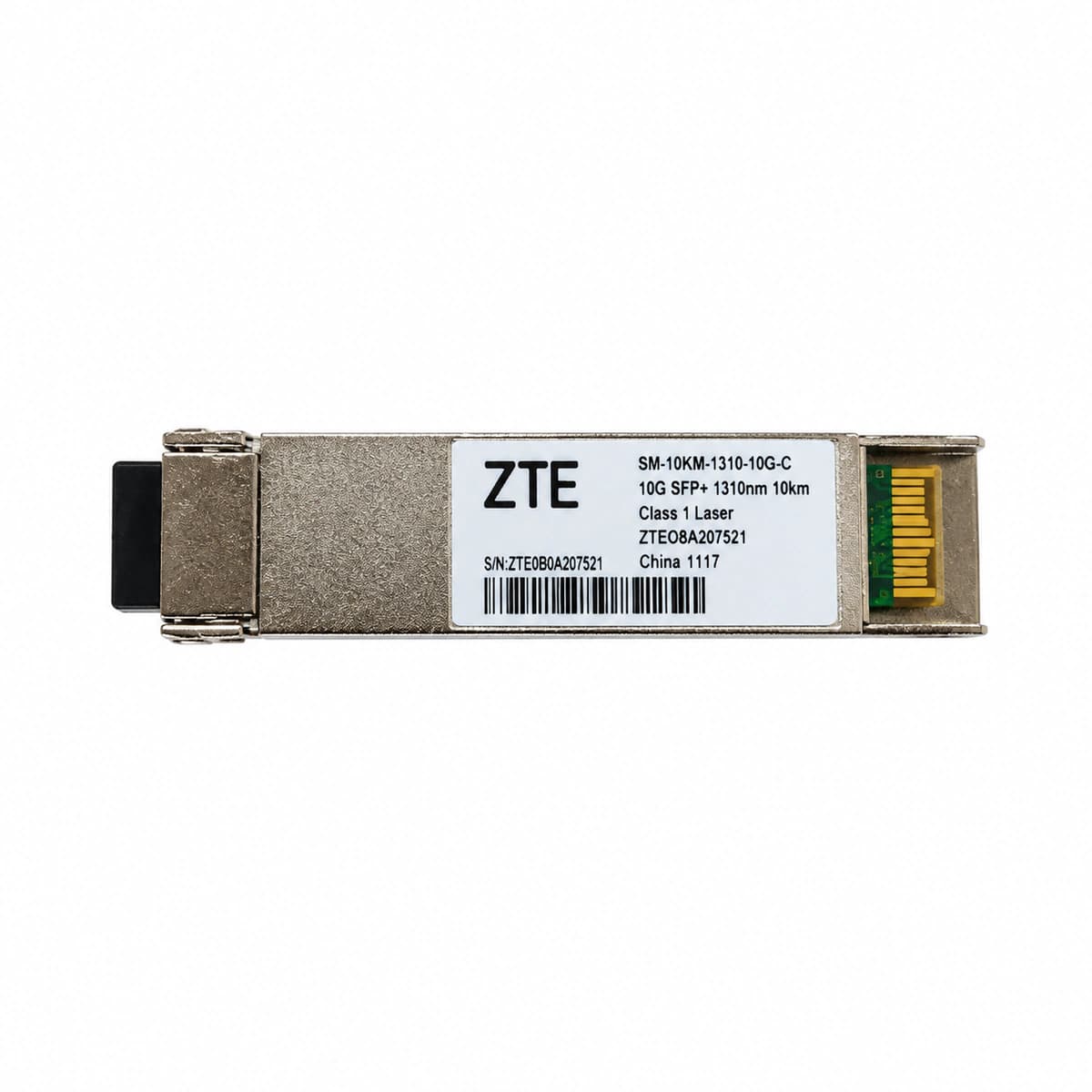
View full product specifications
ZTE 10G SFP+ 10km Official Product View 4

Information below comes from the current product catalogue. Confirm the controller, software version and configuration of the installed equipment separately.

Physical Form Factor
SFP+
Data Rate
10.3125 Gbps
Central Wavelength
1310 nm
Maximum Distance
10 km
Fiber Type
Single-Mode Fiber (SMF) (SMF)
Optical Connector
Duplex LC (blue pull tab)

Alarms & troubleshooting

RX_LOS (Loss of Optical Input Signal)
Port LINK LED Off, System ALM LED Solid Red
No optical power received. Causes include remote TX disabled, broken/bent patch cord, dirty LC connector, or peer optic failure.
1. Run 'show interface optical-transceiver' via CLI to verify if RX power is below the -15.8 dBm sensitivity threshold. 2. Verify the remote peer interface is enabled and TX is emitting. 3. Inspect and clean optical connectors and transceivers with a fiber scope and one-click cleaner. 4. Measure physical optical line power with an optical power meter to rule out cable rupture or excessive attenuation. 5. Replace the SFP+ module if the physical fiber link verifies normal.
TX_FAULT_BIAS (Laser Bias Current High / Transmitter Fault)
Port LINK LED Blinking Red or Off, System ALM LED Solid Amber/Red
Internal DFB laser degradation over time causing APC to overdrive bias current beyond high warning threshold, or internal driver/circuit fault triggering hardware TX Fault.
1. Execute 'show interface optical-transceiver detail' to retrieve DDM stats for TX Bias Current and TX Output Power. 2. If TX Bias Current exceeds 70mA while TX power drops below -8.2 dBm, the laser is degraded. 3. Execute 'shutdown' followed by 'no shutdown' on the interface to reset the optical driver. 4. If the condition persists and link drops, replace the SFP+ 10km optical transceiver immediately.
TEMP_HIGH (SFP+ Module Operating High Temperature Alarm)
Chassis FAN speed ramps to 100%, System ALM LED Solid Amber
Transceiver internal temperature exceeded the 75°C threshold due to high ambient room temperature, clogged air filters, airflow blockage, or chassis fan failure.
1. Check room precision cooling and verify cold aisle temperature is maintained between 20°C and 25°C. 2. Verify chassis fan operation via 'show environment fan' and replace faulty fan trays. 3. Clean rack air filters and clear obstructions around intake and exhaust vents. 4. If only one module is overheating in a cool chassis, swap the module to verify if its internal power converter is defective.
CRC_ERR_FLAP (Port Link Flapping & CRC Error Threshold Exceeded)
Port LINK LED Intermittently Toggling Green and Off, ACT LED Irregular Blink
RX optical power hovering near critical sensitivity threshold (-13 dBm to -15 dBm), scratched/contaminated fiber endface, or physical fiber stress causing excessive bit errors and link drops.
1. Execute 'show interface <port>' to verify if Input errors, CRC, and framing errors are incrementing. 2. Check DDM optical power graphs to verify if RX power fluctuates around the threshold. 3. Clean the patch cord ferrules using a dry cassette cleaner and replace the optical coupler/adapter if necessary. 4. Swap with a known-good patch cord to eliminate micro-bending or damaged fiber jumpers. 5. Adjust carrier-delay damping timers if needed and check the remote SFP+ transmitter stability.
RX_PWR_LOW (Optical RX Power Below Warning/Alarm Threshold)
Port LINK LED Solid Green, System ALM LED Solid Amber
Optical RX power has fallen below the DDM Low Alarm/Warning limit (-14.4 dBm to -15.8 dBm). Caused by span attenuation, optical patch panel loss, or weak transmitter at the remote end.
1. Run 'show interface optical-transceiver detail' to check current RX Optical Power against DDM thresholds. 2. Perform an OTDR test on the physical optical fiber to identify high-loss splices or macro-bends. 3. Clean all patch panel (ODF) mating sleeves and replace suspect interconnect jumpers. 4. If outside plant fiber loss is normal but remote TX power is low, replace the remote SFP+ module. 5. If the link length exceeds 10km, upgrade the optics to 40km (ER) or 80km (ZR) specifications.

Access Complete Maintenance & Full Alarm Troubleshooting Manual

This page lists high-frequency critical alarm codes commonly encountered in field maintenance. Comprehensive manufacturer troubleshooting matrices, board-level repair guides, detailed electrical schematics, and firmware commissioning manuals are delivered alongside equipment upon formal project procurement, accompanied by dedicated FAE technical support.

Share on-site information

  1. 01

    Identify the exact model

    Record the nameplate, system model and controller or module model.

  2. 02

    Keep the alarm details

    Record the full alarm text, indicator colour, timing and whether it persists.

  3. 03

    Describe recent changes

    Note recent replacements, software updates or configuration changes.

Record information visible in the existing interface. Electrical measurements, disassembly and replacement should follow the applicable manufacturer's manual and be performed by qualified personnel.

Your model and these details will be added to the enquiry form for you to review before sending.

Related technical articles

Browse the technical guides or send a question about this model.

View all articles

Need a replacement module or supporting equipment?

Confirm the full model, system configuration and compatibility requirements before enquiring about suitable products.

Ask about suitable products

Have a model and an on-site issue?

Share the exact model, alarm text and observed symptoms to help identify relevant information and compatibility requirements.

Request technical support