ZTE / Optical communications and networking

ZTE 10G SFP+ 1.4km Industrial Equipment information & support

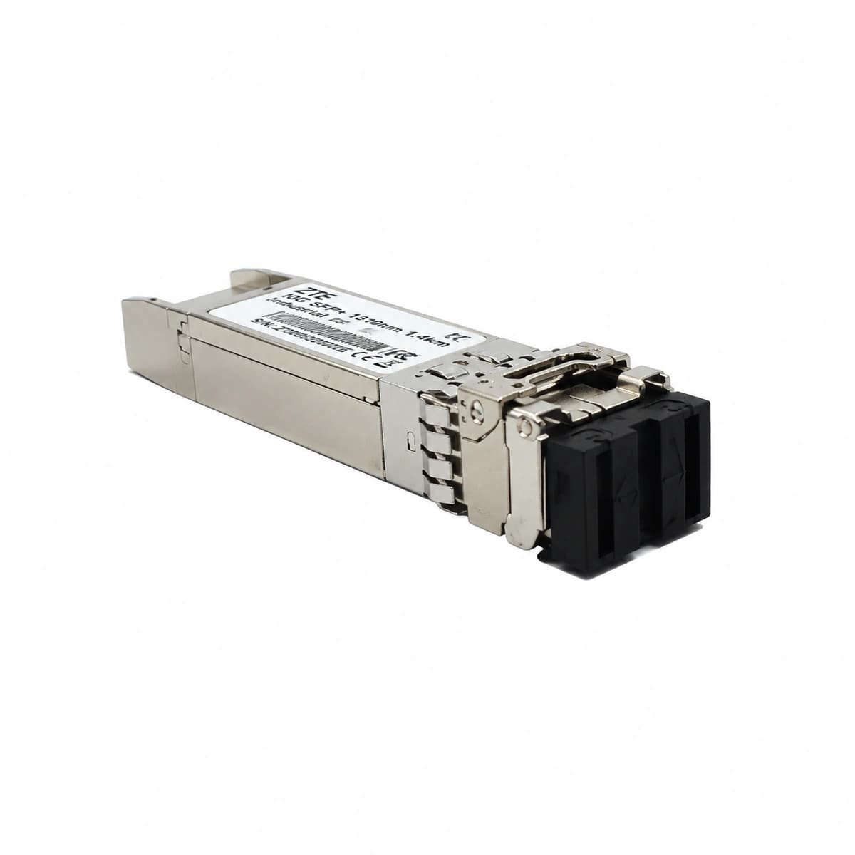
The ZTE 10G SFP+ 1310nm 1.4km Industrial (SM-1.4KM-1310-10G-I) is an industrial-hardened optical transceiver operating across an extreme -40°C to +85°C temperature range up to 1.4km over single-mode fiber with duplex LC connectors.

Equipment information

Brand
ZTE
Equipment model
ZTE 10G SFP+ 1.4km Industrial
Equipment type
Optical communications and networking
Controller / software version
Confirm against the installed equipment
View full product specifications
ZTE 10G SFP+ 1.4km Industrial Official Product View 2

Information below comes from the current product catalogue. Confirm the controller, software version and configuration of the installed equipment separately.

Physical Form Factor
SFP+
Data Rate
9.8 ~ 10.3125 Gbps
Central Wavelength
1310 nm
Maximum Distance
1.4 km
Fiber Type
Single-Mode Fiber (SMF) (SMF)
Optical Connector
Duplex LC Connector

Alarms & troubleshooting

OPT_LOS (Optical RX Loss of Signal)
Port LINK/ACT LED off, System ALM LED solid red
Fiber break, dirty/damaged LC connector, excessive fiber bending loss, or remote peer transmitter powered off/disabled.
1. Query DDM via CLI/NMS to verify if RX power is below the sensitivity threshold (-14.4 dBm); 2. Inspect and clean optical LC connectors and bulkheads using a dry fiber cleaner; 3. Measure optical attenuation with an OPM/OTDR to detect fiber breaks or excessive losses; 4. Confirm remote transceiver TX is enabled and transmitting normally.
TX_BIAS_HIGH (Laser Bias Current High)
Port LINK/ACT LED slow blinking amber, System ALM LED solid amber
Semiconductor Laser Diode (LD) aging, driver compensation circuit saturation, or degradation caused by long-term high-temperature stress.
1. Execute CLI commands to read DDM Tx Bias Current and confirm if it exceeds upper threshold (typically >70 mA); 2. Check Tx output power to determine if optical emission degradation has occurred; 3. Schedule a maintenance window to hot-swap with an identical industrial-grade (-40 to 85°C) 10G SFP+ spare; 4. Verify DDM parameters and error-free link operation after module replacement.
DDM_TEMP_HIGH (SFP+ Over-Temperature Alarm)
System ALM LED solid amber, chassis fan trays running at full speed
Deteriorated cabinet/shelter ventilation, clogged dust filters, fan tray failure, or localized thermal trapping exceeding industrial rating (>85°C).
1. Collect DDM temperature telemetry to check if it exceeds the +85°C industrial limit; 2. Inspect host chassis fan status and verify air intake/exhaust paths are clear of obstructions; 3. Clean air filters and inspect cabinet climate unit (HVAC/heat exchanger) operation; 4. Redistribute high-power optics across slots or replace the module if the internal sensor is defective.
PORT_CRC_ERR (Port CRC Alignment Error Over-Threshold)
Port LINK/ACT LED alternating yellow/green flash, packet loss present
RX optical power operating near sensitivity margin, contaminated fiber end-face inducing jitter, dispersion degradation, or oxidized SFP+ edge-connector pins.
1. Inspect interface statistics (`show interface`) to verify if CRC/FCS error counters are incrementing; 2. Check DDM Rx optical power to ensure it sits comfortably within the optimal range (-1 dBm to -11 dBm); 3. Clean the LC patch cable end-faces and reseat the SFP+ module in the cage; 4. Replace the patch cord; if bit errors persist, swap the SFP+ transceiver to eliminate internal CDR faults.
I2C_COMM_FAIL (Transceiver I2C Read Failure / Unrecognized)
Port LINK/ACT LED off, Slot FAULT LED blinking
Improper transceiver seating, MOD_ABS pin failure, corrupted internal EEPROM/MCU firmware, or host I2C bus lockup.
1. Remove transceiver and inspect PCB edge fingers and cage connector for bent pins or debris; 2. Re-insert firmly and latch the bail clasp to ensure physical engagement of the MOD_ABS pin; 3. Execute CLI commands to test if vendor and serial info can be read across the I2C bus; 4. Cross-test module in an adjacent port; if still unreadable, replace the defective SFP+ module.

Access Complete Maintenance & Full Alarm Troubleshooting Manual

This page lists high-frequency critical alarm codes commonly encountered in field maintenance. Comprehensive manufacturer troubleshooting matrices, board-level repair guides, detailed electrical schematics, and firmware commissioning manuals are delivered alongside equipment upon formal project procurement, accompanied by dedicated FAE technical support.

Share on-site information

  1. 01

    Identify the exact model

    Record the nameplate, system model and controller or module model.

  2. 02

    Keep the alarm details

    Record the full alarm text, indicator colour, timing and whether it persists.

  3. 03

    Describe recent changes

    Note recent replacements, software updates or configuration changes.

Record information visible in the existing interface. Electrical measurements, disassembly and replacement should follow the applicable manufacturer's manual and be performed by qualified personnel.

Your model and these details will be added to the enquiry form for you to review before sending.

Related technical articles

Browse the technical guides or send a question about this model.

View all articles

Need a replacement module or supporting equipment?

Confirm the full model, system configuration and compatibility requirements before enquiring about suitable products.

Ask about suitable products

Have a model and an on-site issue?

Share the exact model, alarm text and observed symptoms to help identify relevant information and compatibility requirements.

Request technical support