ZTE / Power management

CSU401S Equipment information & support

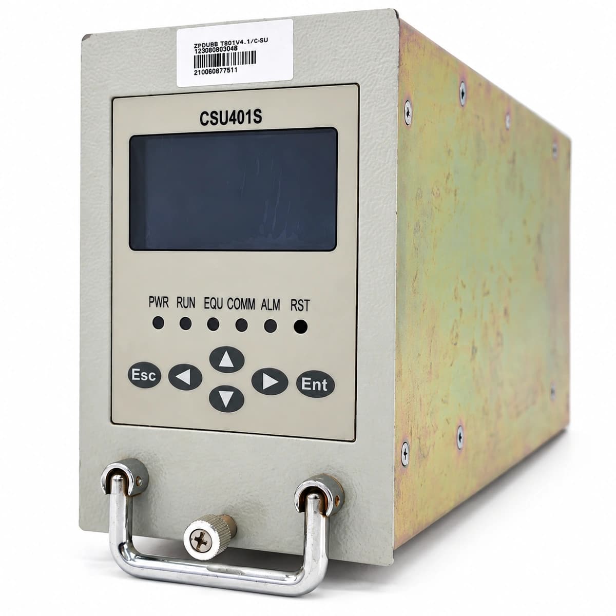
The ZTE CSU401S is a carrier-grade centralized supervisory controller designed for ZXDU series DC power systems, managing AC/DC distribution, rectifiers, and intelligent battery operations.

Equipment information

Brand
ZTE
Equipment model
CSU401S
Equipment type
Power management
Controller / software version
Confirm against the installed equipment
View full product specifications
ZTE CSU401S Official Product View 3

Information below comes from the current product catalogue. Confirm the controller, software version and configuration of the installed equipment separately.

Alarms & troubleshooting

AC_FAIL (Mains Failure Alarm)
ALM Red LED solid on, RUN Green LED slow flashing
Utility grid power blackout, main AC input circuit breaker tripped, or phase voltage dropped below the low-voltage cutoff threshold.
1. Measure phase-to-neutral and phase-to-phase voltages at the AC distribution box using a multimeter. 2. Check whether the upstream AC mains breaker or AC surge arrester breaker has tripped. 3. If AC input voltage is normal, verify that the ribbon cable between the CSU401S and the AC sampling board is firmly seated.
LLVD_ACT (Load Low Voltage Disconnect Active)
ALM Red LED solid on, internal buzzer continuous beep
Batteries discharged down to the pre-configured LLVD voltage threshold (typically 44.0V), triggering the DC contactor to drop non-critical loads.
1. Immediately start and connect a mobile emergency diesel generator to restore AC supply. 2. Review current DC busbar voltage and LLVD threshold settings via the CSU401S LCD/web menu. 3. After AC is restored, verify that the contactor recloses automatically; if not, execute contactor test and check coil control drive circuit.
REC_COMM_FAIL (Rectifier Communication Failure)
ALM Amber LED solid on, corresponding rectifier fault LED blinking
CAN communication bus interruption between rectifier and CSU401S, missing bus termination resistor, bent pins on backplane connector, or slot address conflict.
1. Ensure the rectifier module is fully inserted and the locking latch is properly engaged. 2. Remove the faulty rectifier module and inspect gold finger contacts and backplane connector pins for bends or damage. 3. Execute a module scan from the CSU401S; if unresolved, swap the rectifier into an adjacent functional slot to isolate backplane vs module defect.
BATT_TEMP_HIGH (Battery High Temperature Alarm)
ALM Amber LED solid on
Air conditioning unit failure in battery room, battery thermal runaway, or damaged/short-circuited negative temperature coefficient (NTC) temperature sensor.
1. Measure physical battery casing and terminal temperatures using an infrared thermometer to rule out thermal runaway or swelling. 2. Inspect site air conditioner cooling operation and cabinet ventilation. 3. Disconnect the temperature sensor and measure its resistance with a multimeter to verify against standard NTC curves; replace sensor if open/shorted.
SPD_FAIL (Surge Protective Device Failure)
ALM Amber LED solid on, SPD module physical inspection window turned red
High-energy lightning surge or transient grid voltage strike degrading internal MOVs, triggering the dry-contact signaling circuit of the surge arrester.
1. Inspect the mechanical indicator windows on each phase of the AC SPD cartridges to confirm which module has turned red. 2. Check the microswitch and signal cabling connected from the SPD base to the CSU401S dry contact input port. 3. Trip the SPD backup breaker, hot-swap the damaged MOV cartridge with an authentic ZTE-rated spare, and confirm the alarm clears automatically.

Access Complete Maintenance & Full Alarm Troubleshooting Manual

This page lists high-frequency critical alarm codes commonly encountered in field maintenance. Comprehensive manufacturer troubleshooting matrices, board-level repair guides, detailed electrical schematics, and firmware commissioning manuals are delivered alongside equipment upon formal project procurement, accompanied by dedicated FAE technical support.

Share on-site information

  1. 01

    Identify the exact model

    Record the nameplate, system model and controller or module model.

  2. 02

    Keep the alarm details

    Record the full alarm text, indicator colour, timing and whether it persists.

  3. 03

    Describe recent changes

    Note recent replacements, software updates or configuration changes.

Record information visible in the existing interface. Electrical measurements, disassembly and replacement should follow the applicable manufacturer's manual and be performed by qualified personnel.

Your model and these details will be added to the enquiry form for you to review before sending.

Related technical articles

Browse the technical guides or send a question about this model.

View all articles

Need a replacement module or supporting equipment?

Confirm the full model, system configuration and compatibility requirements before enquiring about suitable products.

Ask about suitable products

Have a model and an on-site issue?

Share the exact model, alarm text and observed symptoms to help identify relevant information and compatibility requirements.

Request technical support