Vertiv / DC power systems

Vertiv Liebert LTS UF-LTS16-1P Static Transfer Switch Equipment information & support

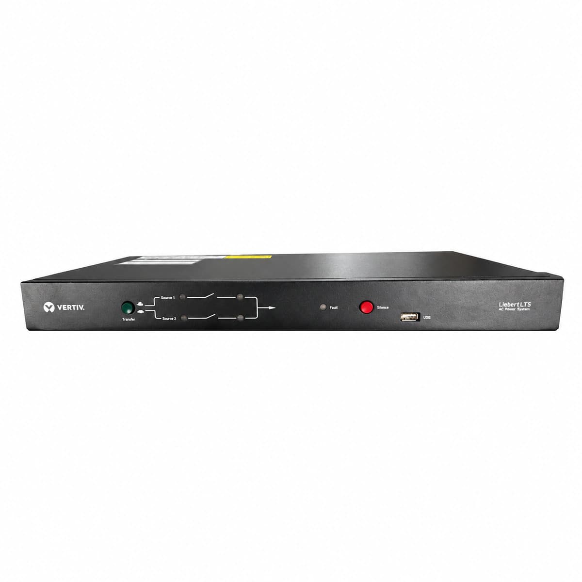
The Vertiv Liebert LTS UF-LTS16-1P is an industrial-grade 16A 1U rackmount Static Transfer Switch (STS) engineered with high-speed Silicon Controlled Rectifier (SCR) architecture, delivering seamless sub-5ms power transfers between dual independent AC inputs to guarantee power continuity for mission-critical single-cord telecom and IT systems.

Equipment information

Brand
Vertiv
Equipment model
Vertiv Liebert LTS UF-LTS16-1P Static Transfer Switch
Equipment type
DC power systems
Controller / software version
Confirm against the installed equipment
View full product specifications
Vertiv Liebert LTS UF-LTS16-1P 16A 1U Rackmount Static Transfer Switch (STS)

Information below comes from the current product catalogue. Confirm the controller, software version and configuration of the installed equipment separately.

Physical Form Factor
Standard 1U 19-inch compact rack-mount chassis structure
Rated Switching Current
16A Single-Phase Static Transfer Switch (STS)
Transfer Time
≤ 5 ms (ultra-fast seamless dual-power synchronized transfer via thyristors)
Dual AC Input Spec
Dual-redundant single-phase 220V/230V AC independent power inputs (Source 1 & 2)
Output Distribution Sockets
Multiple IEC 320 C13 / C19 branch outlet distribution with overload protection
Status LED Indicators
Front panel clear LED indication for power flow path and fault alarm status

Alarms & troubleshooting

SRC1_ABNORMAL (Source 1 Out of Tolerance)
S1 LED Off or Amber flashing, Alarm LED Amber solid, intermittent buzzer
Primary Source 1 (S1) experienced AC outage, undervoltage (<180VAC), overvoltage (>260VAC), or frequency deviation outside tolerance window (50/60Hz ±5%).
1. Measure True RMS L-N voltage and frequency at S1 input terminals; 2. Inspect upstream circuit breaker and PDU feeding S1 for trips or loose wiring; 3. Verify S1 voltage tolerance thresholds via LTS software interface; 4. Once supply stabilizes, verify automatic or manual retransfer back to S1.
SRC2_ABNORMAL (Source 2 Out of Tolerance)
S2 LED Off, Alarm LED Amber solid, loss of redundancy warning
Secondary Source 2 (S2) tripped breaker, disconnected input cord, or voltage/frequency out of specification, resulting in lost power redundancy.
1. Check upstream branch breaker supplying Source 2 from alternate UPS/PDU; 2. Measure S2 input terminal voltage to ensure it is within 220V/230V ±10%; 3. Reseat S2 IEC input power connector and tighten screw terminals; 4. Verify S2 LED turns solid green indicating dual redundancy restoration.
OUTPUT_OVERLOAD (Output Current Overload)
Output Load LED Red solid, Alarm LED Red flashing, continuous buzzer tone
Downstream IT load exceeds 16A rated capacity of UF-LTS16-1P (continuous >100% or severe inrush), risking thermal breaker trip or transfer inhibition.
1. Check rack PDU ammeters to identify aggregate IT current draw; 2. Immediately shed non-critical servers or compute loads to bring current below 13A (80% load factor); 3. Investigate concurrent server boot inrush currents; 4. If the rear thermal circuit protector tripped, wait for cooldown and push to reset.
SRC_UNSYNC (Sources Out of Synchronization)
S1 and S2 LEDs Green, Sync LED Off or Amber flashing, Alarm LED Amber solid
Phase angle displacement between Source 1 and Source 2 exceeds transfer window limit (typically >30°), inhibiting rapid seamless transfer to prevent transformer saturation.
1. Determine if dual inputs originate from unsynchronized UPS sources or grid/generator split feeds; 2. If dual UPS are used, check upstream LBS (Load Bus Synchronizer) operation; 3. Note that in unsynchronized state, STS falls back to break-before-make transfer (8-16ms); 4. Re-establish upstream phase sync to clear alarm.
STS_FAULT (Internal SCR / Switch Hardware Fault)
Fault LED Red solid, Output LED off or flashing, continuous rapid audible alarm
Internal Silicon-Controlled Rectifier (SCR) short circuit, open circuit, gate driver circuitry failure, or contactor welding on power path.
1. Immediately check downstream critical load status without attempting forced manual switching; 2. If an external bypass switch is present, transfer load to maintenance bypass; 3. Open both upstream input breakers (S1/S2) to isolate LTS and apply LOTO safety protocols; 4. Check SCR diode continuity with a multimeter; 5. Contact Vertiv Technical Support for unit RMA or replacement.

Access Complete Maintenance & Full Alarm Troubleshooting Manual

This page lists high-frequency critical alarm codes commonly encountered in field maintenance. Comprehensive manufacturer troubleshooting matrices, board-level repair guides, detailed electrical schematics, and firmware commissioning manuals are delivered alongside equipment upon formal project procurement, accompanied by dedicated FAE technical support.

Share on-site information

  1. 01

    Identify the exact model

    Record the nameplate, system model and controller or module model.

  2. 02

    Keep the alarm details

    Record the full alarm text, indicator colour, timing and whether it persists.

  3. 03

    Describe recent changes

    Note recent replacements, software updates or configuration changes.

Record information visible in the existing interface. Electrical measurements, disassembly and replacement should follow the applicable manufacturer's manual and be performed by qualified personnel.

Your model and these details will be added to the enquiry form for you to review before sending.

Related technical articles

Browse the technical guides or send a question about this model.

View all articles

Need a replacement module or supporting equipment?

Confirm the full model, system configuration and compatibility requirements before enquiring about suitable products.

Ask about suitable products

Have a model and an on-site issue?

Share the exact model, alarm text and observed symptoms to help identify relevant information and compatibility requirements.

Request technical support