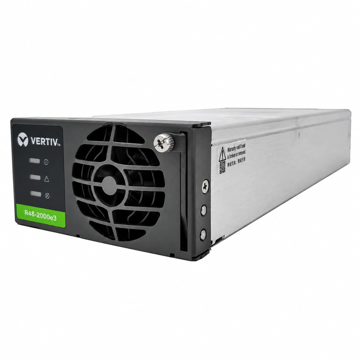
Information below comes from the current product catalogue. Confirm the controller, software version and configuration of the installed equipment separately.
Power Conversion Efficiency
≥96.2%
AC Input Voltage Range
85VAC ~ 300VAC
Nominal DC Output Voltage
-42VDC ~ -58VDC (Nominal -48VDC)
Cooling Method
Front-to-rear air cooling with a temperature-controlled DC fan
AC_IN_FAIL / AC_DERATE (AC Input Abnormal / Loss / Voltage Derating)
Power LED (Green) OFF or flashing; Protection LED (Yellow) steady ON; Fault LED (Red) OFF.
Utility grid blackout, phase loss, loose terminal wiring, or AC input voltage out of operating envelope (<85 VAC causes linear derating or low-voltage cutoff, >290 VAC triggers overvoltage protection).
1. Measure L-N AC voltage at the rectifier slot backplane connector using a True-RMS digital multimeter;
2. Verify AC supply is within the operational range of 85 VAC to 290 VAC;
3. Inspect the upstream AC circuit breaker (MCB) for trip conditions;
4. Retorque AC terminal screws and check for loose neutral connection;
5. If AC input is nominal but module protection LED persists, reseat the module and inspect gold-finger contacts; replace module if defective.
DC_OV_LOCKOUT / HVSD (DC Output Overvoltage Lockout / High Voltage Shutdown)
Power LED (Green) OFF; Fault LED (Red) steady ON (latched); Protection LED (Yellow) OFF.
Internal PWM loop failure, optocoupler feedback breakdown, or bus transient voltage exceeding the hardware High Voltage Shutdown (HVSD) setpoint (typically 59.5 VDC ± 0.5 V). Module latches off to protect telecom loads.
1. Extract the faulted rectifier module from the subrack and trip its AC feed;
2. Wait at least 3 minutes to allow internal high-voltage capacitors to fully discharge;
3. Reinsert the module firmly and re-apply AC power to execute a cold hardware reset;
4. Verify via supervisory controller (e.g., M500S/M830B) that float/equalize target voltage is not misconfigured (>58.5 VDC);
5. If the module instantly relatches with red LED upon restart, internal voltage regulation has failed; replace the unit.
During derating: Power LED (Green) steady ON, Protection LED (Yellow) steady ON; During thermal shutdown: Power LED OFF, Protection LED (Yellow) ON/flashing, Fault LED (Red) steady ON.
Ambient temperature exceeding 55°C, clogged cabinet air filters, reverse hot-air recirculation, or internal heatsink thermistor (NTC) detecting power MOSFET/PFC junction temperature exceeding design safety threshold (>105°C triggers shutdown).
1. Check site HVAC cooling system to guarantee subrack intake temperature is below 35°C;
2. Remove and clean cabinet front intake dust filters using compressed air or vacuum;
3. Inspect subrack air baffles and install blanking panels over empty slots to avoid hot air loops;
4. Allow module heatsink to cool; verify Protection LED clears and module re-engages normal output automatically;
5. If intake air is cool and fan spins properly but over-temperature persists, replace module due to degraded heatsink paste or faulty internal NTC.
Fault LED (Red) flashing (0.5 Hz to 1 Hz); Protection LED (Yellow) steady ON or flashing; Power LED (Green) steady ON.
Internal brushless DC fan impeller mechanically stalled by foreign debris, bearing seizure, or loss of tachometer pulse (Hall sensor open-circuit), resulting in measured RPM dropping below 70% of target duty-cycle.
1. Visually inspect the front grille of the module to verify if the impeller is physically jammed by cables or debris;
2. De-energize module and spin blades gently using a non-conductive probe to verify free mechanical rotation;
3. Re-power module and observe self-test rotation; unusual grinding noise indicates bearing wear;
4. Unscrew front bezel and verify 4-pin fan connector is firmly seated on the internal PCB header;
5. If obstruction is cleared and connections are intact but the fan fault persists, replace the fan assembly or swap the module.
CAN_COMM_FAIL / I_SHARE_ERR (CAN-bus Communication Lost & Active Current Share Failure)
Power LED (Green) flashing (0.5 Hz); Protection LED (Yellow) flashing; Fault LED (Red) OFF.
CAN_H / CAN_L differential line open circuit, oxidized backplane signal connector pins, missing 120-ohm bus terminating resistor, or autonomous current-share circuit fault causing module output imbalance (>10% deviation from average).
1. Check SCU/controller display to see if a single rectifier is offline or the entire CAN bus has failed;
2. Reseat module and clean the backplane communication gold pins with isopropyl alcohol;
3. Measure resistance across CAN_H and CAN_L with power off (nominal value should be ~60 ohms due to dual parallel 120-ohm terminations);
4. Verify if module falls back to standalone default autonomous output (53.5 VDC);
5. Swap module to an adjacent slot; if the fault follows the module, internal CAN transceiver (PCA82C250/SN65HVD230) is damaged; replace module.
Access Complete Maintenance & Full Alarm Troubleshooting Manual
This page lists high-frequency critical alarm codes commonly encountered in field maintenance. Comprehensive manufacturer troubleshooting matrices, board-level repair guides, detailed electrical schematics, and firmware commissioning manuals are delivered alongside equipment upon formal project procurement, accompanied by dedicated FAE technical support.
Record the nameplate, system model and controller or module model.
02
Keep the alarm details
Record the full alarm text, indicator colour, timing and whether it persists.
03
Describe recent changes
Note recent replacements, software updates or configuration changes.
Record information visible in the existing interface. Electrical measurements, disassembly and replacement should follow the applicable manufacturer's manual and be performed by qualified personnel.
Related technical articles
Browse the technical guides or send a question about this model.