Vertiv / Power management

NetSure 731 A61-S4 Equipment information & support

The Vertiv NetSure 731 A61-S4 is a high-density 11U rack-mount -48VDC telecom power subrack engineered to house up to 10 high-efficiency R48-3200e or R48-3500e rectifiers, delivering up to 600A output.

Equipment information

Brand
Vertiv
Equipment model
NetSure 731 A61-S4
Equipment type
Power management
Controller / software version
Confirm against the installed equipment
View full product specifications
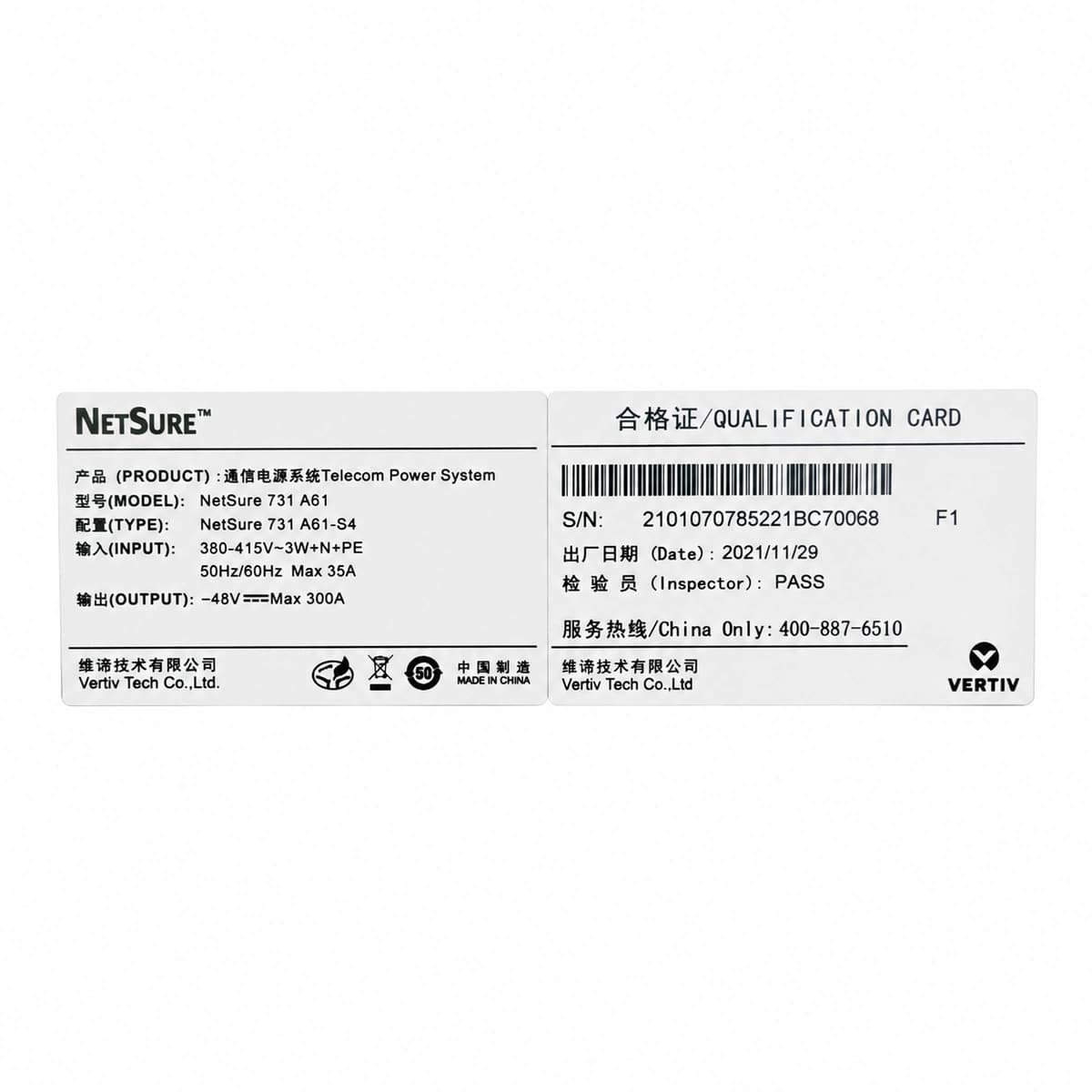
Vertiv NetSure 731 A61-S4 Official White Background Photo View 1

Information below comes from the current product catalogue. Confirm the controller, software version and configuration of the installed equipment separately.

AC Input Voltage Range
85VAC ~ 300VAC (3-Phase 5-Wire 380VAC) VAC
Smart Monitoring Controller
NCU / M830B Central Monitoring System
Cooling Method
Isolated duct forced air cooling
Nominal Output Voltage
-48VDC VDC
Rated Output Current
600A (System Capacity 28.8kW)
Managed Rectifier Capacity
6 Slots for R48-3200e / R48-3500e3 Modules

Alarms & troubleshooting

RECT-FAIL
Module Alarm LED Steady Red; Controller Alarm LED Flashing Red
Internal power stage failure, auxiliary SMPS fault, fan lock-rotor, or sustained output overvoltage shutdown.
Check for airflow blockages in the module chassis; query the specific fault sub-code via controller; reseat the rectifier to verify connector integrity; if the red fault LED persists upon re-insertion, replace the rectifier module.
AC-FAIL
Rectifier AC Green LEDs OFF; Controller Alarm LED Amber/Red
Complete utility power outage, upstream AC input breaker trip, damaged/shorted surge protection device (SPD), or phase voltage below 85VAC.
Verify grid availability; inspect the subrack main AC input breaker and upstream distribution board; measure phase-to-neutral and phase-to-phase voltages with a DMM; inspect SPD status indicator flag and replace if blown.
DC-VOLT-LOW
Controller Alarm LED Steady Red; Internal Audible Buzzer Active
Prolonged AC mains outage causing deep battery discharge below low-voltage threshold, multiple rectifier failures, or load exceeding total rectifier output rating.
Dispatch emergency mobile generator to restore AC feed immediately; shed secondary non-vital loads manually if LLVD has not tripped; check LLVD contactor operational state; plug in spare rectifier modules into vacant slots.
BATT-TEMP-HIGH
Controller Warning LED Steady Amber
Battery compartment air conditioner failure, restricted cabinet ventilation, excessive ambient site temperature, or internal thermal runaway in compromised cells.
Inspect battery room HVAC equipment; scan all battery monoblocs using a thermal imaging camera to detect isolated thermal anomalies; isolate the defective battery branch circuit breaker if cell bulging or thermal runaway is confirmed; verify sensor attachment position.
SPD-FAIL
Surge Protector Window Shows Red Flag; Controller Warning LED Amber
AC or DC surge protection device intercepted heavy lightning surge or grid switching transient; internal metal oxide varistors (MOV) degraded, shorted, or thermal disconnector opened.
Verify that grounding resistance meets telecom standards (typically ≤5Ω); inspect the SPD dry-contact alarm signal harness; safely extract the tripped SPD cartridge using insulated tooling and replace it with an identical OEM-rated spare module.

Access Complete Maintenance & Full Alarm Troubleshooting Manual

This page lists high-frequency critical alarm codes commonly encountered in field maintenance. Comprehensive manufacturer troubleshooting matrices, board-level repair guides, detailed electrical schematics, and firmware commissioning manuals are delivered alongside equipment upon formal project procurement, accompanied by dedicated FAE technical support.

Share on-site information

  1. 01

    Identify the exact model

    Record the nameplate, system model and controller or module model.

  2. 02

    Keep the alarm details

    Record the full alarm text, indicator colour, timing and whether it persists.

  3. 03

    Describe recent changes

    Note recent replacements, software updates or configuration changes.

Record information visible in the existing interface. Electrical measurements, disassembly and replacement should follow the applicable manufacturer's manual and be performed by qualified personnel.

Your model and these details will be added to the enquiry form for you to review before sending.

Related technical articles

Browse the technical guides or send a question about this model.

View all articles

Need a replacement module or supporting equipment?

Confirm the full model, system configuration and compatibility requirements before enquiring about suitable products.

Ask about suitable products

Have a model and an on-site issue?

Share the exact model, alarm text and observed symptoms to help identify relevant information and compatibility requirements.

Request technical support