Vertiv / Site energy systems

NetSure 731 A41-S8 Equipment information & support

The Vertiv NetSure 731 A41-S8 is a standalone telecom DC power plant cabinet rated at -48V 600A, supporting eight high-efficiency R48 rectifiers and an advanced NCU supervisory unit.

Equipment information

Brand
Vertiv
Equipment model
NetSure 731 A41-S8
Equipment type
Site energy systems
Controller / software version
Confirm against the installed equipment
View full product specifications
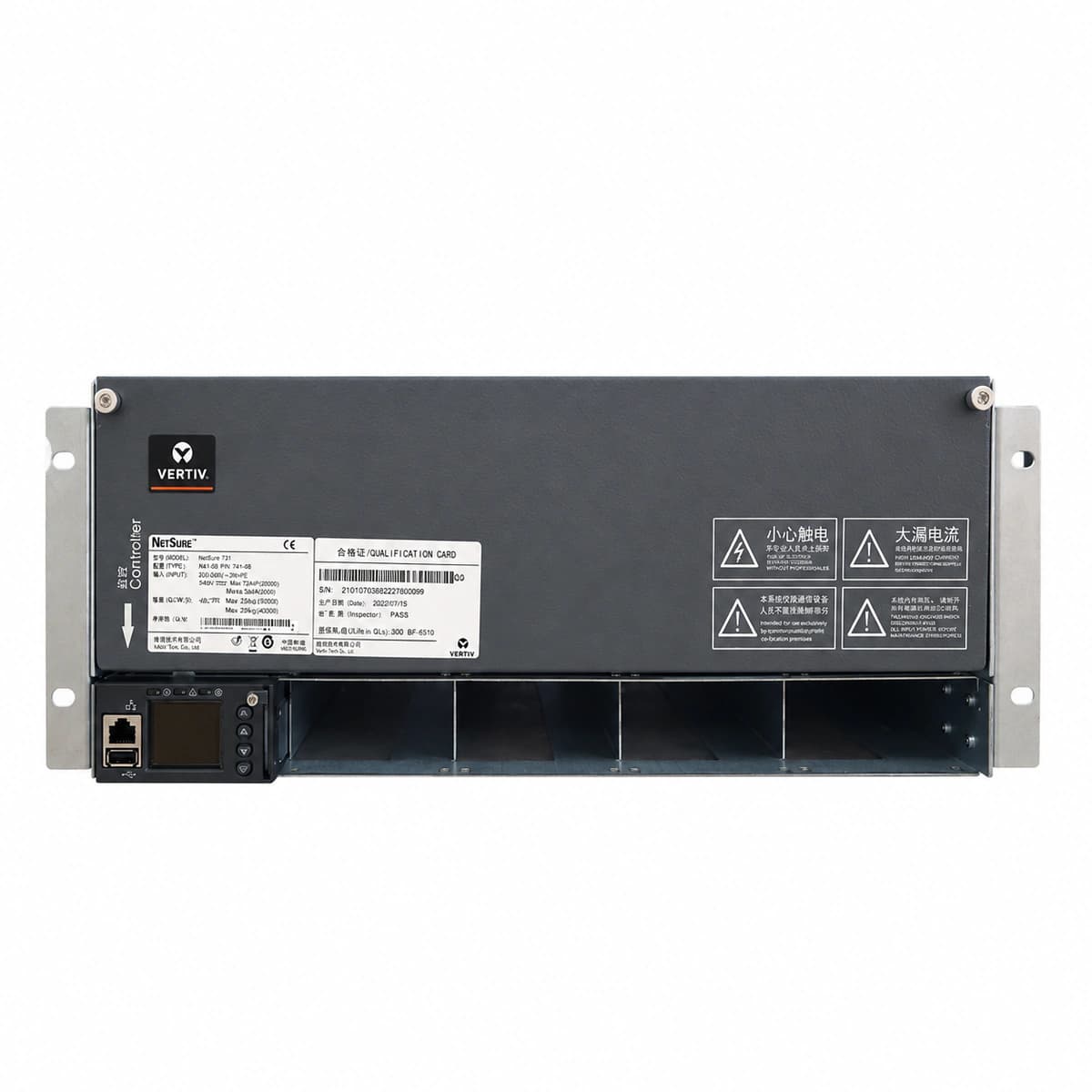
NetSure 731 A41-S8 Official Product View 1

Information below comes from the current product catalogue. Confirm the controller, software version and configuration of the installed equipment separately.

System Output Capacity
600 A
Nominal Output Voltage
-48 VDC
Output Voltage Range
-42 ~ -58 VDC
AC Input Voltage Range
85 ~ 300 VAC (three-phase input)
Rectifier Module Slots
8 Slots (Supports R48-3500e3 / R48-4000e)
System Monitoring Controller
NCU (NetSure Control Unit) monitoring with color touchscreen

Alarms & troubleshooting

AC_FAIL (AC Mains Failure / Phase Loss)
Controller Red ALARM LED solid ON; Rectifier green AC LED OFF, yellow ALARM LED solid ON
Upstream grid power outage, AC distribution circuit breaker trip, loose input terminal connection, or phase voltage dropped below 80VAC
1. Measure AC phase-to-neutral and phase-to-phase voltages to confirm levels are within 85VAC–290VAC; 2. Inspect upstream input breakers and SPD disconnectors; reset if tripped after clearing faults; 3. Check and torque AC terminal connections on the NetSure shelf; 4. If AC voltage is nominal but specific modules report phase loss, hot-swap the affected rectifier module.
RECT_HVSD (Rectifier DC Output Overvoltage Lockout)
Faulty rectifier red FAULT LED solid ON; Controller panel shows MAJOR/CRITICAL alarm
Internal PWM regulation loop failure, active current sharing loop malfunction, or external DC voltage spike triggering hardware HVSD latch (>59.5VDC)
1. Unseat the latched rectifier module, wait 2 minutes for internal capacitors to discharge, and reseat to reset the hardware lockout; 2. If HVSD recurs upon reboot, measure DC bus voltage using a calibrated multimeter; 3. Access controller menus to verify float and boost charge setpoints do not exceed limits (normally <58.5VDC); 4. If bus voltage is normal but the unit locks immediately, replace the damaged rectifier.
DC_LOW_LLVD (DC Low Voltage & Load Disconnect)
Controller red CRITICAL LED flashing; Buzzer ON; Cabinet LLVD contactor open status indicated
Prolonged mains outage resulting in battery depletion below threshold (typically 44.0VDC), triggering LLVD contactor disconnection to protect non-critical loads and battery life
1. Deploy an emergency mobile diesel generator to restore AC power immediately; 2. Ensure rectifiers power up and deliver charge current to raise DC bus voltage; 3. When bus voltage recovers above the reconnect threshold (typically >48.0VDC), verify LLVD contactor reclosure; 4. If the contactor fails to pick up automatically, test controller relay driver outputs and contactor coil resistance.
COMM_FAIL (Rectifier CAN Bus Communication Failure)
Controller yellow MAJOR LED solid ON; Affected rectifier yellow ALARM LED flashing
Loose backplane CAN bus flat cable, open terminal resistor (120 Ohm), damaged transceiver in rectifier, or module slot addressing conflict
1. Verify integrity of CAN communication cables interconnecting controller and subrack backplane; 2. Measure resistance between CAN_H and CAN_L with power off (nominal value ~60 Ohms with two 120 Ohm terminators); 3. Swap the reporting module into an alternate slot to isolate backplane pin fault vs. module CAN transceiver fault; 4. Reseat controller module or execute software bus scan via NCU web interface.
FAN_FAIL (Rectifier Fan Blocked / Tachometer Fault)
Rectifier yellow ALARM LED blinking or red FAULT solid ON; Output current derated automatically
Severe dust accumulation blocking rectifier air inlet filter, physical blockage of fan blades, bearing seizure, or fan tachometer circuit failure
1. Visually inspect the front air grill of the rectifier and remove dust, lint, or physical obstructions; 2. Hot-extract the module and verify if the fan rotor spins freely without mechanical resistance; 3. Clean the internal heatsink airflow tunnel using dry compressed air; 4. Re-insert the module; if the speed sensor alarm persists, replace the fan sub-assembly or replace the entire rectifier module.

Access Complete Maintenance & Full Alarm Troubleshooting Manual

This page lists high-frequency critical alarm codes commonly encountered in field maintenance. Comprehensive manufacturer troubleshooting matrices, board-level repair guides, detailed electrical schematics, and firmware commissioning manuals are delivered alongside equipment upon formal project procurement, accompanied by dedicated FAE technical support.

Share on-site information

  1. 01

    Identify the exact model

    Record the nameplate, system model and controller or module model.

  2. 02

    Keep the alarm details

    Record the full alarm text, indicator colour, timing and whether it persists.

  3. 03

    Describe recent changes

    Note recent replacements, software updates or configuration changes.

Record information visible in the existing interface. Electrical measurements, disassembly and replacement should follow the applicable manufacturer's manual and be performed by qualified personnel.

Your model and these details will be added to the enquiry form for you to review before sending.

Related technical articles

Browse the technical guides or send a question about this model.

View all articles

Need a replacement module or supporting equipment?

Confirm the full model, system configuration and compatibility requirements before enquiring about suitable products.

Ask about suitable products

Have a model and an on-site issue?

Share the exact model, alarm text and observed symptoms to help identify relevant information and compatibility requirements.

Request technical support