Vertiv / Power management

NetSure 701 A41-S6 Equipment information & support

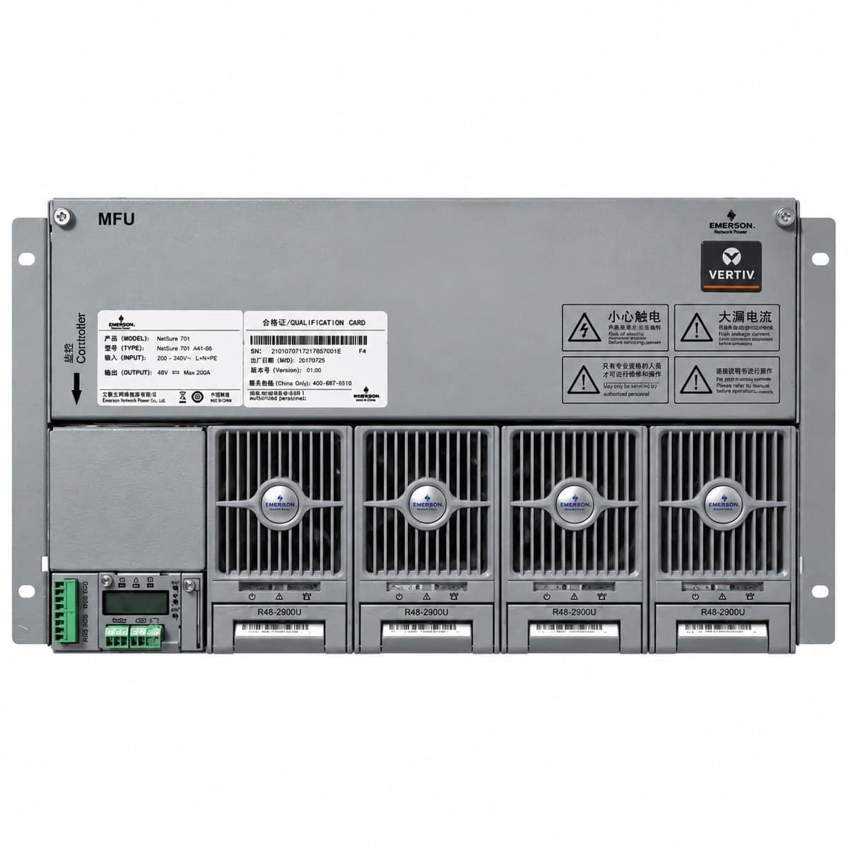
The Vertiv NetSure 701 A41-S6 is a 6U 19-inch rack-mounted -48VDC telecom-grade power system engineered for up to 400A output, integrating high-efficiency rectifier slots, AC/DC distribution, and an M530S/NCU controller.

Equipment information

Brand
Vertiv
Equipment model
NetSure 701 A41-S6
Equipment type
Power management
Controller / software version
Confirm against the installed equipment
View full product specifications
Vertiv NetSure 701 A41-S6 Official White Background Photo View 1

Information below comes from the current product catalogue. Confirm the controller, software version and configuration of the installed equipment separately.

AC Input Voltage Range
85VAC ~ 300VAC (3-Phase 380V / 1-Phase 220V) VAC
Smart Monitoring Controller
M830B / NCU Controller
Cooling Method
Forced Air Cooling
Nominal Output Voltage
-48VDC VDC
Rated Output Current
400A (System Capacity 19.2kW)
Managed Rectifier Capacity
4 Slots for R48-2900U / R48-3200e Modules

Alarms & troubleshooting

AC_POWER_FAIL
Controller CRITICAL Red LED solid ON, Rectifier Yellow LED flashing or all LEDs OFF
Mains utility outage, upstream AC distribution breaker tripping, or AC input phase voltage dropping below 80VAC threshold.
Measure True-RMS AC voltage across input terminals L-N / L-L; inspect external ATS contactor state and upstream breaker handles; if full outage persists, audit DC discharge rate on battery and dispatch mobile generator standby.
DC_VOLTAGE_LOW
Controller MAJOR Yellow or CRITICAL Red LED illuminated
Sustained battery discharge reduced DC bus voltage below under-voltage threshold (typically <45.0VDC), rectifiers offline, or load severely exceeds rectifier output capacity.
Verify if AC power can be restored immediately; check individual rectifier module operational LEDs; if bus approaches LLVD disconnect limits, manually drop secondary non-critical circuits to extend transmission uptime; restore rectifiers and initiate boost charge with current limit.
RECTIFIER_FAULT
Faulty Rectifier Red Fault LED solid ON, Controller MAJOR Yellow LED ON
Internal rectifier PFC failure, DC/DC converter power stage hardware damage, heatsink over-temperature trip, or output over-voltage hardware shutdown latch.
Access the M530S menu to identify the exact sub-fault register; extract the faulty module from its slot, wait 30 seconds for internal capacitor discharge, then reseat it firmly to cycle logic; if the red fault LED persists, replace with a known-good spare unit.
RECTIFIER_COMM_FAIL
Rectifier Yellow LED flashing, Controller MAJOR Yellow LED ON
Internal CAN bus communication lost between supervisory controller and rectifier slot, dirty/oxidized backplane pins, or address clash in auto-numbering sequence.
Reseat the rectifier module firmly until front latch clicks securely; pull the module and visually inspect slot guide pins and female backplane pins for debris or misalignment; verify controller ribbon flat-cable seating; trigger 'Re-addressing / Search Rectifiers' on the controller interface.
BLVD_DISCONNECT
Controller CRITICAL Red LED flashing, audible buzzer sounding, BLVD contactor feedback indicator OFF
Protracted AC utility outage caused battery voltage to collapse to critical terminal cut-off (typically <43.2VDC), tripping magnetic latching contactor to prevent cell destruction.
Immediately inject AC supply via mobile diesel generator or utility recovery; upon rectifier ramp-up, the M530S will energize the contactor driver coil once bus voltage recovers; if the contactor stays locked open, inspect battery terminal polarity and voltage, then execute 'Force Battery Contactor Close' from the M530S maintenance menu while strictly enforcing a 0.1C recharge current limit.

Access Complete Maintenance & Full Alarm Troubleshooting Manual

This page lists high-frequency critical alarm codes commonly encountered in field maintenance. Comprehensive manufacturer troubleshooting matrices, board-level repair guides, detailed electrical schematics, and firmware commissioning manuals are delivered alongside equipment upon formal project procurement, accompanied by dedicated FAE technical support.

Share on-site information

  1. 01

    Identify the exact model

    Record the nameplate, system model and controller or module model.

  2. 02

    Keep the alarm details

    Record the full alarm text, indicator colour, timing and whether it persists.

  3. 03

    Describe recent changes

    Note recent replacements, software updates or configuration changes.

Record information visible in the existing interface. Electrical measurements, disassembly and replacement should follow the applicable manufacturer's manual and be performed by qualified personnel.

Your model and these details will be added to the enquiry form for you to review before sending.

Related technical articles

Browse the technical guides or send a question about this model.

View all articles

Need a replacement module or supporting equipment?

Confirm the full model, system configuration and compatibility requirements before enquiring about suitable products.

Ask about suitable products

Have a model and an on-site issue?

Share the exact model, alarm text and observed symptoms to help identify relevant information and compatibility requirements.

Request technical support