Vertiv / Power management

NetSure 531 A31-S2 Equipment information & support

The Vertiv NetSure 531 A31-S2 is a high-density, 5U 19-inch subrack -48V DC power system delivering up to 120A output capacity for telecom network infrastructure.

Equipment information

Brand
Vertiv
Equipment model
NetSure 531 A31-S2
Equipment type
Power management
Controller / software version
Confirm against the installed equipment
View full product specifications
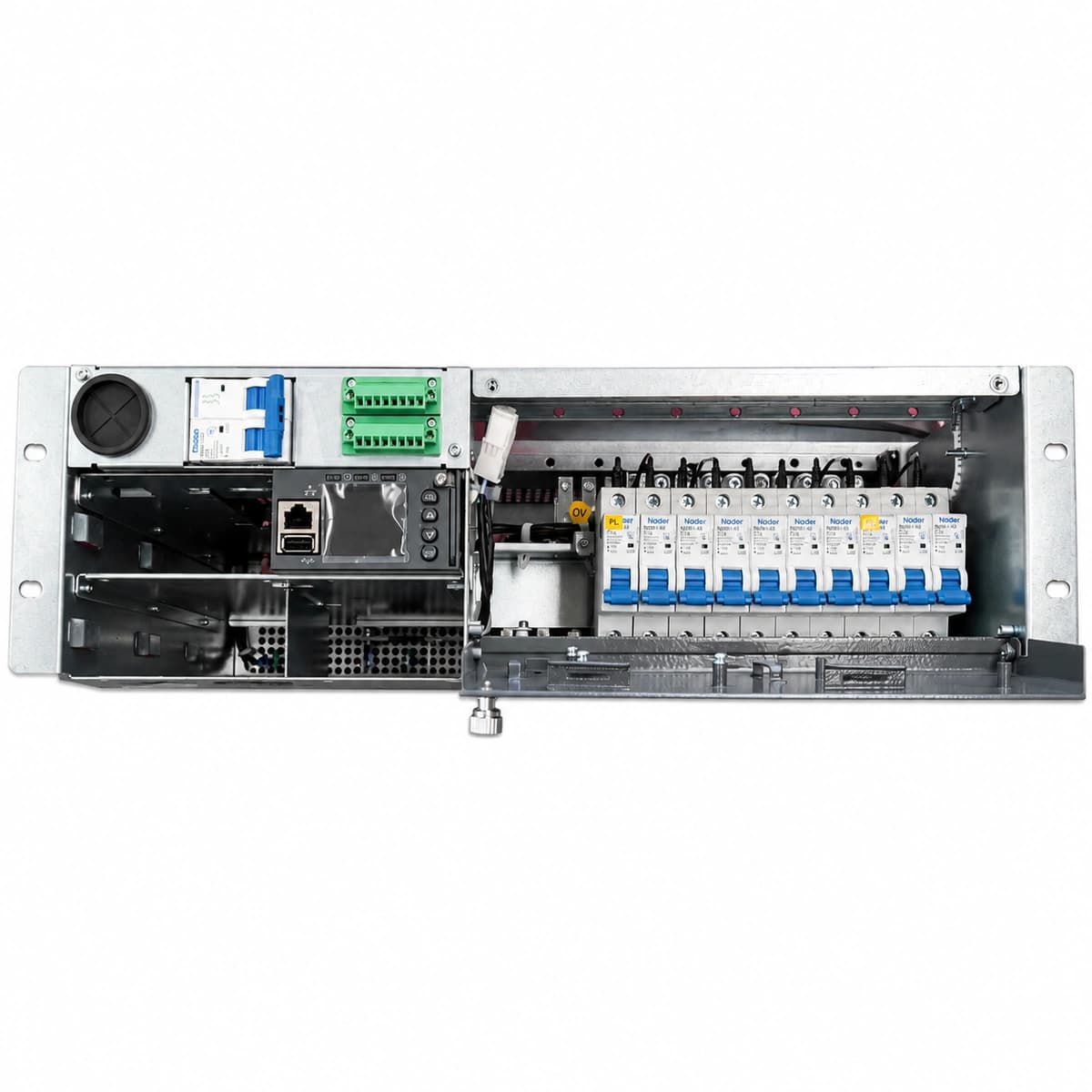
Vertiv NetSure 531 A31-S2 Official White Background Photo View 3

Information below comes from the current product catalogue. Confirm the controller, software version and configuration of the installed equipment separately.

AC Input Voltage Range
85VAC ~ 300VAC (Nominal 220VAC) VAC
Smart Monitoring Controller
M221S / M522B Controller Unit
Cooling Method
Temperature-controlled DC fan cooling
Nominal Output Voltage
-48VDC VDC
Rated Output Current
120A (System Capacity 5.8kW)
Managed Rectifier Capacity
3 Slots for R48-2000e3 / R48-2900U Modules

Alarms & troubleshooting

AC_MAINS_FAIL
Controller Prompt/Alarm LED Red/Yellow ON, Rectifier Green Power LED OFF, Yellow Protection LED Flashing
Complete utility blackout, upstream AC input circuit breaker tripped, or AC input phase voltage outside acceptable operating window (<85VAC or >300VAC).
1. Measure phase-to-neutral and phase-to-phase voltages at the AC distribution terminals using a calibrated multimeter; 2. Verify state of the main AC input breaker and SPD surge protective device; 3. If grid voltage is within 85-300VAC, inspect internal AC harness connection to rectifiers; 4. During blackout, monitor battery discharge rate and estimated autonomy on the controller, deploying emergency generator if required.
RECTIFIER_COMM_FAIL
Controller Prompt Yellow LED ON, Affected Rectifier Yellow Protection LED Flashing
Loss of internal CAN bus communication between the supervision controller and specific rectifier, oxidized backplane connector pins, or damaged module interface logic.
1. Unlatch and reseat the affected rectifier module, inspecting rear edge-connector pins for bent contacts, debris, or oxidation; 2. Push firmly into subrack and engage latch completely; 3. If alarm persists, insert module into an alternate spare slot to isolate module hardware failure from backplane CAN trace fault; 4. Re-run rectifier auto-enumeration/discovery in the controller menu; 5. Replace faulty rectifier or backplane if communications cannot be restored.
DC_VOLTAGE_LOW
Controller Alarm Red LED Solid ON, Internal Buzzer Sounding, Rectifiers may show Yellow LED
Extended AC outage causing deep battery discharge, multiple rectifier failures rendering remaining capacity insufficient for the load, or short circuit / extreme overload dragging the DC bus below the critical threshold (typically <-45.0VDC).
1. Immediately check utility AC power status and portable generator availability; 2. Inspect rectifiers for fault LEDs or tripped AC branch breakers; replace failed modules immediately; 3. Verify total real-time load current against available rectifier capacity; 4. Prepare load-shedding procedures by manually disconnecting non-essential auxiliary circuits before LLVD/BLVD total station shutdown occurs; 5. Measure load branches for localized short circuits.
BLVD_DISCONNECT
Controller Alarm Red LED Solid ON, Bus Voltage Drops to Zero (if no rectifiers active), Continuous Audible Alarm
Battery string reached the critical low-voltage cutoff threshold (e.g., -43.2VDC), triggering the BLVD contactor to trip and isolate batteries, or contactor auxiliary contact / drive circuit failure.
1. Treat as the highest priority service outage. Immediately restore AC power (via grid or emergency generator); 2. Once rectifiers power up and raise the DC bus above the recovery threshold (-48VDC), verify that the BLVD contactor automatically latches closed; 3. If rectifiers are healthy but contactor remains open, access controller maintenance menu to execute a manual contactor close test, and measure 48V coil drive voltage across contactor terminals; 4. Measure open-circuit voltage on battery terminals to verify no dead cells or reversed polarity exist before allowing heavy recharge current.
BATT_TEMP_HIGH
Controller Prompt Yellow LED ON, UI Displays Battery Temperature Warning
Battery compartment air conditioner or fan tray failure, extreme site ambient temperature, loose/shorted NTC sensor probe, or onset of battery thermal runaway due to internal cell defect (typically exceeding +50°C threshold).
1. Use a calibrated handheld infrared thermometer to scan the surface of every battery block, identifying any hot spots or abnormal thermal gradients; 2. Inspect cabinet ventilation paths, fan trays, and heat exchangers or air conditioners; clean clogged intake air filters; 3. Cross-reference controller displayed temperature against physical laser measurements to verify NTC probe calibration; 4. If bulging or casing deformation is observed, immediately clamp the charge current limit on the controller (e.g., reduce to 0.05C10), disable equalize charging, and replace the failing cell monobloc.

Access Complete Maintenance & Full Alarm Troubleshooting Manual

This page lists high-frequency critical alarm codes commonly encountered in field maintenance. Comprehensive manufacturer troubleshooting matrices, board-level repair guides, detailed electrical schematics, and firmware commissioning manuals are delivered alongside equipment upon formal project procurement, accompanied by dedicated FAE technical support.

Share on-site information

  1. 01

    Identify the exact model

    Record the nameplate, system model and controller or module model.

  2. 02

    Keep the alarm details

    Record the full alarm text, indicator colour, timing and whether it persists.

  3. 03

    Describe recent changes

    Note recent replacements, software updates or configuration changes.

Record information visible in the existing interface. Electrical measurements, disassembly and replacement should follow the applicable manufacturer's manual and be performed by qualified personnel.

Your model and these details will be added to the enquiry form for you to review before sending.

Related technical articles

Browse the technical guides or send a question about this model.

View all articles

Need a replacement module or supporting equipment?

Confirm the full model, system configuration and compatibility requirements before enquiring about suitable products.

Ask about suitable products

Have a model and an on-site issue?

Share the exact model, alarm text and observed symptoms to help identify relevant information and compatibility requirements.

Request technical support