Vertiv / Precision air conditioning

Liebert PEX2 Precision AC Equipment information & support

The Vertiv Liebert PEX2 is an industrial-grade, direct expansion (DX) precision cooling system engineered for medium-to-large data centers and core telecom facilities. Featuring Copeland high-efficiency scroll compressors, EC backward-curved plug fans, and the iCOM intelligent control framework, it delivers an ultra-high sensible heat ratio (SHF ≥ 0.92) and 24/7 continuous thermal heat load management under harsh operating conditions.

Equipment information

Brand
Vertiv
Equipment model
Liebert PEX2 Precision AC
Equipment type
Precision air conditioning
Controller / software version
Confirm against the installed equipment
View full product specifications
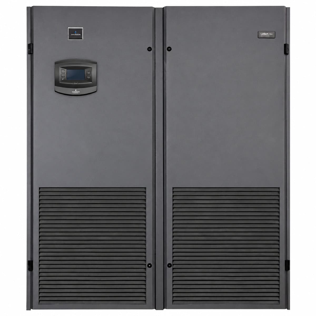
Vertiv Liebert PEX2 Series Precision Data Center Air Conditioner (20kW-100kW/EC Fan/R410A/iCOM) Official Studio Photo 1

Information below comes from the current product catalogue. Confirm the controller, software version and configuration of the installed equipment separately.

Rated Cooling Capacity
20kW ~ 100kW (Multiple Cooling Capacities Optional)
Sensible Heat Ratio (SHF)
≥ 0.92 (High Sensible Heat Ratio for Data Center)
Airflow Delivery & Fan Type
Downflow / Upflow Optional, EC Variable Speed Fan
Grid Power Supply System
380V AC 50Hz (3-Phase 5-Wire)
Refrigerant Type
R410A Eco Refrigerant
Compressor Type
Copeland High-Efficiency Scroll Compressor

Alarms & troubleshooting

HP_ALARM (High Discharge Pressure)
Alarm LED solid red, Run LED off, audible buzzer active
Outdoor condenser fouled/blocked, condenser fan failed, electronic expansion valve closed, refrigerant overcharge, or faulty HP switch
1. Inspect outdoor condenser coils and clean off debris/dirt buildup. 2. Verify outdoor fan circuit breaker and check the 0-10V fan speed control signal. 3. Connect manifold gauges to verify discharge pressure limits (R410A). 4. Wait for system equalization, depress the manual HP switch reset button, and clear alarm on iCOM controller.
LP_ALARM (Low Suction Pressure)
Alarm LED flashing red, affected circuit locked out
Refrigerant leak, restricted liquid line filter-drier, heavily clogged air filters causing poor evaporator load, or low-ambient start fault
1. Check return air filters and evaporator coil; replace clogged air filters. 2. Check temperature drop across liquid line filter-drier; replace if temperature difference is noticeable. 3. Use an electronic leak detector on brazed joints/valves, fix leaks, and recharge refrigerant to target superheat. 4. Verify low-pressure switch electrical wiring and low-pressure start bypass timer settings in iCOM.
AIR_LOSS (Loss of Airflow / Fan Failure)
Alarm LED solid red, unit full shutdown lockout
EC fan motor driver fault, fan circuit breaker tripped, differential air pressure switch pickup tube detached/clogged, or switch threshold drift
1. Check the fan circuit breakers and confirm three-phase input balance. 2. Inspect EC fan communication bus (Modbus/PWM) and check LED indicators on the motor drive. 3. Inspect the pitot pressure sensing tubes for cracks, disconnections, or liquid blockage. 4. Manually rotate fan wheel to confirm free rotation without mechanical binding; recalibrate or replace pressure switch.
COND_PUMP_FAIL (Condensate Pump Failure / High Water Level)
Alarm LED solid amber, cooling and humidification interlocked off
Condensate drain line clogged, pump power supply disconnected or motor burnt out, high-level float switch stuck, or faulty check valve
1. Inspect drain pan for accumulated water and clear algae, slime, or debris from drain port. 2. Verify power supply to condensate pump and check internal thermal overload switch. 3. Manually move the float switch up and down while checking continuity with a multimeter. 4. Flush discharge check valve and external drain line; reset alarm once water level normalizes.
TH_SENS_FAIL (Return Air Temp/Humidity Sensor Fault)
Alarm LED solid amber, unit switches to emergency fail-safe mode
RS-485/CAN bus communication loss to combo sensor, loose signal wiring, sensor DC supply failure, or damaged sensing element due to condensation
1. Inspect sensor terminal block (V+, GND, A+, B-) for secure connection and shield grounding. 2. Measure DC supply voltage at the sensor connector (nominally 12V DC or 24V DC). 3. Verify sensor DIP switch address and baud rate settings match the iCOM controller setup. 4. If bus voltage and wiring are verified but values read out-of-range or display "--", replace the sensor probe.

Access Complete Maintenance & Full Alarm Troubleshooting Manual

This page lists high-frequency critical alarm codes commonly encountered in field maintenance. Comprehensive manufacturer troubleshooting matrices, board-level repair guides, detailed electrical schematics, and firmware commissioning manuals are delivered alongside equipment upon formal project procurement, accompanied by dedicated FAE technical support.

Share on-site information

  1. 01

    Identify the exact model

    Record the nameplate, system model and controller or module model.

  2. 02

    Keep the alarm details

    Record the full alarm text, indicator colour, timing and whether it persists.

  3. 03

    Describe recent changes

    Note recent replacements, software updates or configuration changes.

Record information visible in the existing interface. Electrical measurements, disassembly and replacement should follow the applicable manufacturer's manual and be performed by qualified personnel.

Your model and these details will be added to the enquiry form for you to review before sending.

Related technical articles

Browse the technical guides or send a question about this model.

View all articles

Need a replacement module or supporting equipment?

Confirm the full model, system configuration and compatibility requirements before enquiring about suitable products.

Ask about suitable products

Have a model and an on-site issue?

Share the exact model, alarm text and observed symptoms to help identify relevant information and compatibility requirements.

Request technical support