Vertiv / UPS power

Liebert EXS 60kVA Integrated UPS System Equipment information & support

The Vertiv Liebert EXS 60kVA is a high-frequency, double-conversion online three-phase uninterruptible power supply (UPS) system integrated with internal input/output breakers and a manual maintenance bypass. Engineered in a monolithic compact cabinet footprint, it supports a flexible 30-to-44 block DC bus battery architecture to deliver clean, continuous AC power for mission-critical IT edge data centers, precision healthcare equipment, and industrial automation facilities.

Equipment information

Brand
Vertiv
Equipment model
Liebert EXS 60kVA Integrated UPS System
Equipment type
UPS power
Controller / software version
Confirm against the installed equipment
View full product specifications
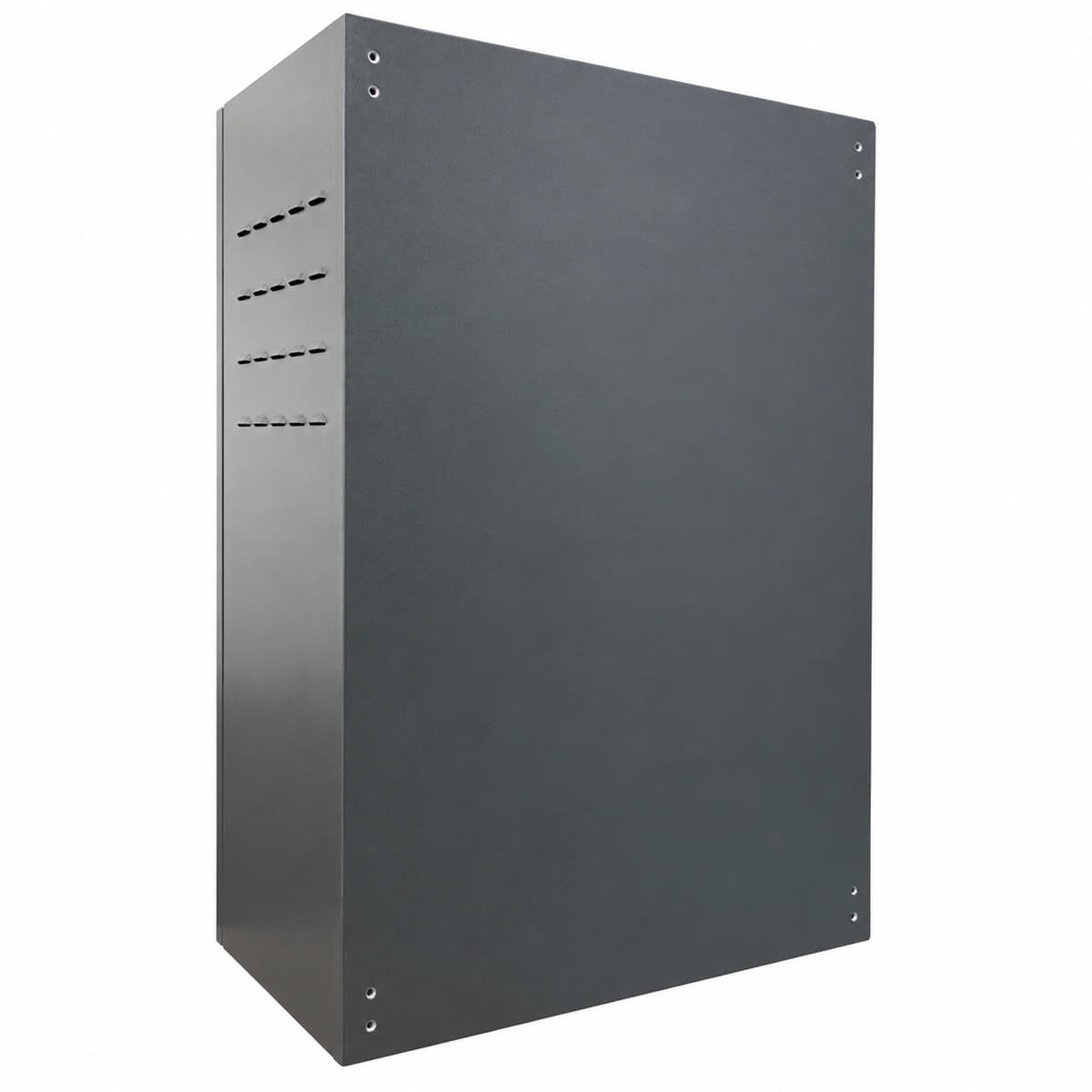
Vertiv Liebert EXS 60kVA Industrial Modular Online 3-Phase UPS Cabinet (60kW / 380-415VAC / 600×850×1600mm)

Information below comes from the current product catalogue. Confirm the controller, software version and configuration of the installed equipment separately.

Rated Capacity kVA/kW
60kVA / 60kW Full Active Power Online Architecture (PF=1.0)
Rated AC Input Voltage
380V / 400V / 415V AC 3-Phase 4-Wire Wide Range
Rated AC Output Voltage
380V / 400V / 415V AC 3-Phase Pure Sine Wave Output
DC Battery Bus Voltage
±240V DC (Configurable 30~44 Lead-Acid/Lithium Cells)
System Comprehensive Efficiency
Up to 96.5% in Double-Conversion Mode, >99% in ECO Mode
Physical Form Factor
Integrated Freestanding Cabinet with Built-in Breakers & Maintenance Bypass

Alarms & troubleshooting

INV_FAULT (Inverter Fault & Bypass Transfer)
Alarm LED solid red, Inverter LED off, Bypass LED solid green, continuous buzzer
IGBT bridge short-circuit, gate driver pulse loss, output AC filter capacitor breakdown, or inverter voltage feedback anomaly
1. Verify that critical loads have safely transferred to static bypass without interruption. 2. Access the LCD display to retrieve event logs and detailed inverter sub-codes (e.g., hardware overcurrent, DC offset). 3. Isolate the system, ensure DC bus capacitors are fully discharged, and measure IGBT module and Hall sensor impedance. 4. Replace defective power semiconductors or driver boards, perform insulation resistance tests, and execute a controlled inverter cold start.
BATT_EOD (Battery End of Discharge Shutdown)
Alarm LED solid red, Battery LED flashing red, Inverter LED off, rapid intermittent buzzer
Prolonged mains outage; battery string reached end-of-discharge cut-off threshold (1.67V-1.75V/cell), triggering low-voltage protection
1. Verify mains supply recovery or start auxiliary diesel generator sets immediately. 2. Once AC input is restored, verify that the rectifier automatically restarts and enters boost/bulk charging mode. 3. If AC mains is healthy but alarm persists, inspect the Battery Circuit Breaker (BCB) auxiliary contact status and DC sense wiring. 4. Measure individual battery cell voltages and internal impedance; replace degraded or sulfated cells.
DC_BUS_OV (DC Bus Overvoltage Lockout)
Alarm LED solid red, Rectifier and Inverter LEDs off, load transferred to bypass
PFC rectifier PWM loss of regulation, severe input transient surge, regenerative back-feed from load dump, or bus voltage sampling board fault
1. Confirm that the system has safely transferred to bypass without interrupting the critical load. 2. Open the AC input breaker and battery breaker; allow high-voltage DC bus capacitors to discharge below safe limits (<36VDC). 3. Measure positive and negative DC bus voltages using a calibrated DMM to verify if the overvoltage was actual or a sensor failure. 4. Inspect PFC driver boards, snubber circuits, and DSP sampling connectors; clear fault registers and execute a controlled restart.
OUT_OVERLOAD (Output Overload & Bypass Degradation)
Alarm LED solid amber, Bypass LED solid amber, intermittent prolonged buzzer
Connected load capacity exceeded 60kVA nominal rating (e.g., >105% sustained or >125% timeout reached), forcing system onto static bypass
1. Inspect the LCD control screen or DCIM to identify phase load percentages and current distribution. 2. Shed non-critical, redundant, or recently added heavy loads to bring total load below 85% capacity. 3. Check phase load balance across downstream distribution boards to prevent single-phase overload trips. 4. Clear the alarm and initiate manual transfer via the LCD screen to return the system from bypass back to inverter mode.
OVERTEMP_FAN_FAIL (Cooling Fan Lockup & Heatsink Over-Temp)
Alarm LED blinking amber, Run LED solid green, periodic warning buzzer
Cooling fan bearing mechanical lockup, tachometer PWM feedback loss (<1000RPM), clogged dust filters, or room ambient temperature exceeding 40°C
1. Inspect front intake dust filters and rear exhaust grills; clean or replace blocked air filter mats immediately. 2. Verify the facility HVAC status and ensure room ambient air temperature is maintained within 20°C–25°C. 3. Navigate to the LCD 'System Diagnostics' menu to inspect individual fan RPM values and locate the faulted fan ID. 4. Replace the defective fan assembly, verify proper harness seating, and confirm that tachometer feedback normalizes and the alarm clears.

Access Complete Maintenance & Full Alarm Troubleshooting Manual

This page lists high-frequency critical alarm codes commonly encountered in field maintenance. Comprehensive manufacturer troubleshooting matrices, board-level repair guides, detailed electrical schematics, and firmware commissioning manuals are delivered alongside equipment upon formal project procurement, accompanied by dedicated FAE technical support.

Share on-site information

  1. 01

    Identify the exact model

    Record the nameplate, system model and controller or module model.

  2. 02

    Keep the alarm details

    Record the full alarm text, indicator colour, timing and whether it persists.

  3. 03

    Describe recent changes

    Note recent replacements, software updates or configuration changes.

Record information visible in the existing interface. Electrical measurements, disassembly and replacement should follow the applicable manufacturer's manual and be performed by qualified personnel.

Your model and these details will be added to the enquiry form for you to review before sending.

Related technical articles

Browse the technical guides or send a question about this model.

View all articles

Need a replacement module or supporting equipment?

Confirm the full model, system configuration and compatibility requirements before enquiring about suitable products.

Ask about suitable products

Have a model and an on-site issue?

Share the exact model, alarm text and observed symptoms to help identify relevant information and compatibility requirements.

Request technical support