Vertiv / Precision air conditioning

Liebert CR060 Equipment information & support

Vertiv Liebert CR060 is the flagship 600mm wide in-row precision cooling unit of the CRV4 series, delivering 62.6kW nominal cooling and 10,250 m³/h airflow for high-density server racks.

Equipment information

Brand
Vertiv
Equipment model
Liebert CR060
Equipment type
Precision air conditioning
Controller / software version
Confirm against the installed equipment
View full product specifications
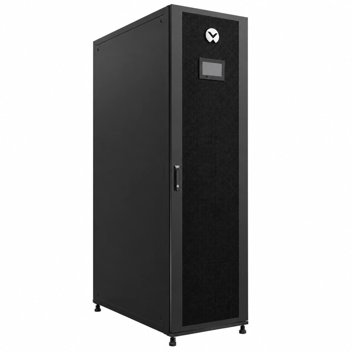
Liebert CR060 Official Product View 1

Information below comes from the current product catalogue. Confirm the controller, software version and configuration of the installed equipment separately.

Full Load Current (FLA)
46.0 A
Rated Cooling Capacity
62.6 kW
Physical Form Factor
300mm / 600mm compact in-row architecture
Sensible Heat Ratio (SHF)
> 0.98 (Ultra-High Sensible Heat Ratio)
Airflow Mode & Volume
Horizontal horizontal air supply close to cabinet heat sources
Compressor Type
DC inverter scroll compressor + EC centrifugal fan

Alarms & troubleshooting

HP_ALARM (Compressor High Discharge Pressure)
iCOM Alarm LED solid Red, audible buzzer continuous
Outdoor condenser heat rejection failure, condenser fan speed controller fault, clogged condenser coil, or excess refrigerant charge triggering HP switch (>2.8 MPa)
1. Inspect outdoor condenser coil for debris or fin blockage; clean with low-pressure water if needed. 2. Measure outdoor fan supply voltage and 0-10V control signal to verify fan speed operation. 3. Compare iCOM discharge pressure reading against manifold gauge to rule out transducer drift. 4. Allow pressure to equalize, press manual reset button on HP switch, and clear alarm on iCOM display.
LP_ALARM (Compressor Low Suction Pressure)
iCOM Alarm LED flashing Red, compressor locked out
Refrigerant loss due to circuit leak, electronic expansion valve (EEV) stuck closed, clogged filter drier, or restricted indoor airflow causing evaporator freeze-up
1. Inspect indoor air filter for clogging; verify EC fans run at required CFM. 2. Use an electronic leak detector across all braze joints, Schrader valves, and fittings to locate leaks. 3. Check suction pressure transducer, EEV step opening, liquid sight glass, and temperature drop across filter drier. 4. Repair leak, evacuate below 500 microns, recharge R410A per unit nameplate, and clear lockout on iCOM.
FAN_FAIL (Loss of Airflow / EC Fan Failure)
iCOM Alarm LED solid Red, affected EC fan diagnostic LED blinks Amber/Red
EC supply fan motor thermal overload, drive internal inverter fault, Modbus control loss, fan breaker trip, or open differential pressure switch
1. Check internal fan circuit breaker (QF) status and measure incoming three-phase voltage balance. 2. Inspect EC fan RS-485 Modbus communication wiring terminals for loose connections. 3. Disconnect power and spin impeller manually to verify mechanical bearing free rotation. 4. If power and 0-10V/Modbus signals are valid but motor fails to run, replace the defective EC fan assembly.
WATER_HIGH (Condensate Pan High Water Level)
iCOM Alarm LED solid Amber, cooling interlocked and inhibited
Condensate pump failure, drainage hose crimped or clogged, stuck check valve, or seized float switch sensor
1. Inspect condensate pump power connector and inline fuse at the base of the Liebert CR060. 2. Inspect drainage hose routing, clear any sludge or debris, and confirm positive drainage drop. 3. Manually toggle float switch mechanism to test dry contact signal state on iCOM controller. 4. If pump motor hums but fails to discharge water, clear impeller debris or replace condensate pump assembly.
SENSOR_FAIL (Temp/Humidity Sensor Open or Comms Loss)
iCOM Alarm LED flashing Amber, unit enters failsafe temperature control mode
Remote rack supply/return air T/H sensor RJ45 patch cable unplugged, CAN/Modbus termination resistor misconfigured, damaged sensing element, or loose connector
1. Verify physical RJ45 connections and cable integrity on 2P/4P remote rack T/H sensor probes. 2. Ensure the 120-ohm terminating resistor DIP switch is enabled only on the last sensor of the CAN bus string. 3. Access iCOM 'Sensor Configuration' menu to verify probe network addressing and polling heartbeat. 4. If cabling is intact but sensor fails to respond, swap with known-good sensor and run auto-discovery.

Access Complete Maintenance & Full Alarm Troubleshooting Manual

This page lists high-frequency critical alarm codes commonly encountered in field maintenance. Comprehensive manufacturer troubleshooting matrices, board-level repair guides, detailed electrical schematics, and firmware commissioning manuals are delivered alongside equipment upon formal project procurement, accompanied by dedicated FAE technical support.

Share on-site information

  1. 01

    Identify the exact model

    Record the nameplate, system model and controller or module model.

  2. 02

    Keep the alarm details

    Record the full alarm text, indicator colour, timing and whether it persists.

  3. 03

    Describe recent changes

    Note recent replacements, software updates or configuration changes.

Record information visible in the existing interface. Electrical measurements, disassembly and replacement should follow the applicable manufacturer's manual and be performed by qualified personnel.

Your model and these details will be added to the enquiry form for you to review before sending.

Related technical articles

Browse the technical guides or send a question about this model.

View all articles

Need a replacement module or supporting equipment?

Confirm the full model, system configuration and compatibility requirements before enquiring about suitable products.

Ask about suitable products

Have a model and an on-site issue?

Share the exact model, alarm text and observed symptoms to help identify relevant information and compatibility requirements.

Request technical support