Huawei / Outdoor power systems

Huawei TP482000B 2.1m Outdoor Cabinet Equipment information & support

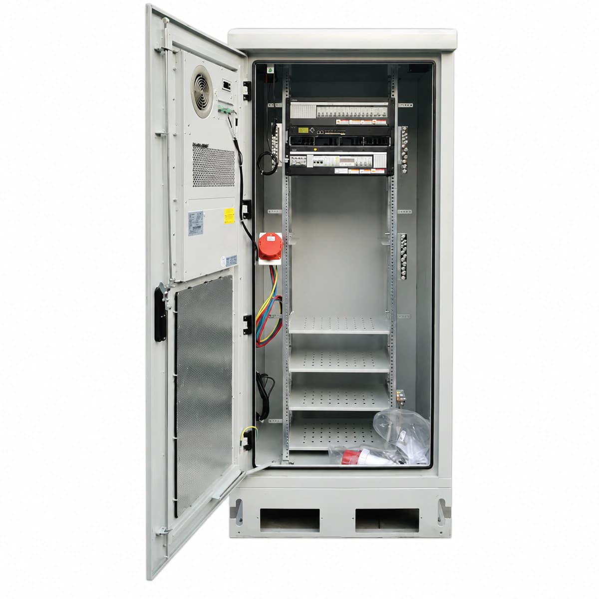
Huawei TP482000B-N20B1 is a 2.1-meter industrial-grade outdoor telecom power cabinet delivering -48V DC rated output up to 2000A with IP55 protection, engineered for 5G macro sites and remote aggregation nodes requiring high-capacity, footprint-free deployment.

Equipment information

Brand
Huawei
Equipment model
Huawei TP482000B 2.1m Outdoor Cabinet
Equipment type
Outdoor power systems
Controller / software version
Confirm against the installed equipment
View full product specifications
Huawei TP482000B-N20B1 2.1m Outdoor Telecom Power Cabinet System -48V 2000A IP55

Information below comes from the current product catalogue. Confirm the controller, software version and configuration of the installed equipment separately.

System Output Capacity
2000A (-48V DC)
Cabinet Physical Height
2.1m Standard High-Protection Outdoor Cabinet (2100×900×900mm)
Ingress Protection Rating
IP55 Industrial All-Weather Dust, Water & Corrosion Proof
Rectifier Module Config
Accommodates up to 40x R4850G2 50A Ultra-HE Rectifier Modules
Thermal Management Architecture
Internal Heat Exchanger + DC Ventilation Dual-Circuit Thermal Control
Smart Controller Unit
SMU02C Integrated Centralized Network Supervisory Unit

Alarms & troubleshooting

AC_FAIL (AC Mains Failure / Phase Loss)
SMU ALM LED solid red; Rectifier RUN LED off, ALM LED solid red
Upstream grid blackout, AC input circuit breaker tripped, loose input wiring terminal, or line voltage below operating threshold (<85VAC)
1. Measure phase-to-phase and phase-to-neutral voltages at the AC input terminal using a calibrated DMM. 2. Check whether the main AC input circuit breakers inside the cabinet are tripped; reset if safe. 3. Verify upstream ATS/distribution switchboard status and torque all AC input terminal connections.
RECT_HVSD (Rectifier DC Overvoltage Lockout)
Rectifier ALM LED solid red, Power LED on, Output LED off; SMU shows critical alarm
Internal voltage regulation loop failure or current-share bus fault driving module DC output above hardware shutdown limit (>59.5VDC)
1. Identify the specific faulted rectifier slot ID from the SMU live alarm menu. 2. Unlock and extract the faulted rectifier; leave disconnected for 3 minutes to discharge internal capacitors, then reseat firmly. 3. If the module trips into HVSD again upon startup, replace it with a functional spare of the same model.
BLVD_ACTIVE (Battery Low Voltage Disconnection)
SMU ALM LED solid red; DC distribution BLVD contactor state indicator triggered; audible buzzer active
Prolonged AC mains outage; battery bank discharge reached critical protection threshold (default 43.2VDC), contactor tripped to protect battery cells
1. Connect an emergency generator or restore AC utility power to allow rectifiers to energize the DC bus. 2. Verify on the SMU that the BLVD contactor recloses automatically once bus voltage climbs above the reconnect threshold (>48VDC). 3. If AC is normal but the contactor stays open, check the contactor coil auxiliary fuse and run manual contactor test via SMU.
RECT_FAN_FAIL (Rectifier Fan Fault)
Rectifier ALM/Fault LED flashing yellow or solid red; SMU displays Major alarm with module derating
Rectifier fan obstructed by debris/dust matting, tachometer speed feedback signal missing, bearing seizure, or clogged air inlet filter
1. Inspect the cabinet air inlet mesh and module front panel; clear any debris, dust mats, or foreign objects. 2. Extract the rectifier module, blow out accumulated dust with dry compressed air, and gently check if blades spin freely. 3. Re-insert the module; if the fan fails to spin during self-test or the alarm persists, replace the fan assembly or the module.
AC_SPD_FAIL (AC Surge Protective Device Failure)
SPD physical indicator window turns from green to red; SMU displays yellow Warning status
Direct lightning hit or severe line surge causing MOV thermal breakdown, tripping the SPD internal thermal disconnector or dedicated breaker
1. Inspect the AC distribution SPD block inside the cabinet to identify modules with a red status flag. 2. Verify whether the SPD upstream backup MCB has tripped and ensure the remote alarm microswitch wiring is secure. 3. Hot-swap the damaged plug-in surge protection cartridge with an identical rating replacement; verify clear status on SMU.

Access Complete Maintenance & Full Alarm Troubleshooting Manual

This page lists high-frequency critical alarm codes commonly encountered in field maintenance. Comprehensive manufacturer troubleshooting matrices, board-level repair guides, detailed electrical schematics, and firmware commissioning manuals are delivered alongside equipment upon formal project procurement, accompanied by dedicated FAE technical support.

Share on-site information

  1. 01

    Identify the exact model

    Record the nameplate, system model and controller or module model.

  2. 02

    Keep the alarm details

    Record the full alarm text, indicator colour, timing and whether it persists.

  3. 03

    Describe recent changes

    Note recent replacements, software updates or configuration changes.

Record information visible in the existing interface. Electrical measurements, disassembly and replacement should follow the applicable manufacturer's manual and be performed by qualified personnel.

Your model and these details will be added to the enquiry form for you to review before sending.

Related technical articles

Browse the technical guides or send a question about this model.

View all articles

Need a replacement module or supporting equipment?

Confirm the full model, system configuration and compatibility requirements before enquiring about suitable products.

Ask about suitable products

Have a model and an on-site issue?

Share the exact model, alarm text and observed symptoms to help identify relevant information and compatibility requirements.

Request technical support