Huawei / Site energy systems

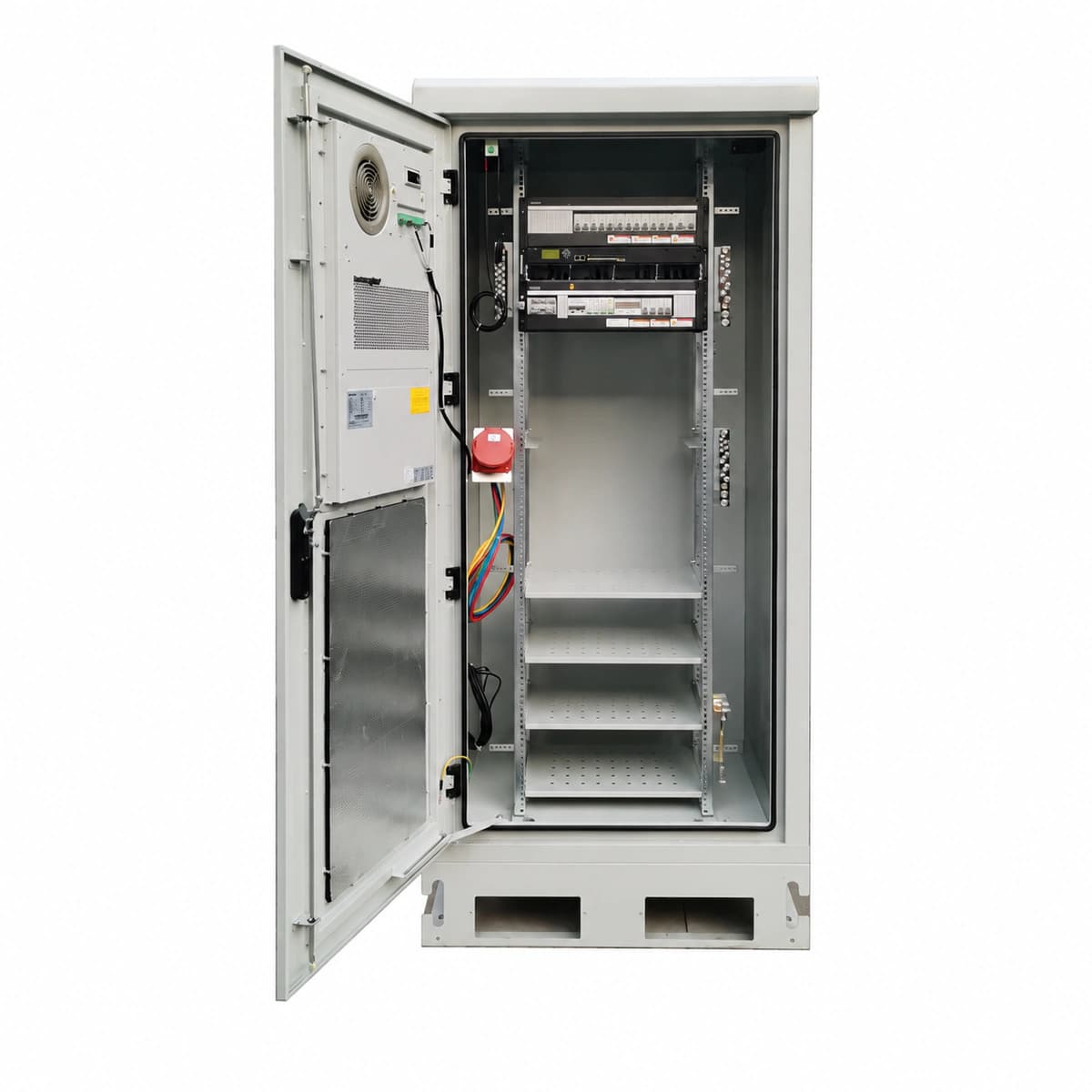
Huawei 2.1m Outdoor Telecom Power Cabinet (ETP4850G) Equipment information & support

The Huawei 2.1m Outdoor Telecom Power Cabinet is an industrial-grade infrastructure integrating the ETP4850G high-efficiency rectifier system and DC PDU within an IP55 dual-compartment enclosure, delivering 200A to 300A regulated -48V DC power for macro base stations and remote aggregation sites.

Equipment information

Brand
Huawei
Equipment model
Huawei 2.1m Outdoor Telecom Power Cabinet (ETP4850G)
Equipment type
Site energy systems
Controller / software version
Confirm against the installed equipment
View full product specifications
Huawei 2.1m Outdoor Telecom Power Cabinet (Integrated ETP4850G -48V DC 200A-300A Dual-Compartment IP55)

Information below comes from the current product catalogue. Confirm the controller, software version and configuration of the installed equipment separately.

Cabinet Physical Height
2.1m Heavy-Duty Outdoor Dual-Bay Compartmentalized Enclosure (2100mm H)
Built-in Power Subsystem
Integrated Huawei ETP4850G 50A Ultra-HE Power Shelf
Total DC Distribution Capacity
200A ~ 300A Generous DC Distribution Capacity & Battery Landings
Thermal Management Architecture
Equipment Bay Heat Exchanger/AC + Battery Bay Direct Air Ventilation
Protection Rating
IP55 Industrial Vandal-Resistant Anti-Corrosion Sealed Structure
Internal Battery Storage Space
Supports Installation of 2~4 Strings of 100Ah~150Ah LiFePO4/VRLA Batteries

Alarms & troubleshooting

AC_FAIL (Mains Failure / AC Input Loss)
SMU controller ALM LED solid red; Rectifier AC power indicators OFF
Commercial utility power blackout, upstream AC breaker tripping, or disconnected ACDU power feed terminals
1. Measure L-N/L-L voltages at the ACDU terminals using a DMM (nominal 176–290 VAC). 2. Verify upstream circuit breakers and internal AC input MCBs are closed. 3. If grid failure persists beyond battery reserve, deploy a mobile generator to ATS inlet.
BLVD_ACT (Battery Low Voltage Disconnect)
SMU ALM LED solid red; DC distribution BLVD contactor tripped
Prolonged AC blackout discharged battery bank below critical threshold (default 43.2 VDC), or battery fuse blown
1. Restore AC power immediately; rectifiers will start and the contactor will automatically re-engage. 2. Verify integrity of all battery fuses/MCBs and sense wire connections with a multimeter. 3. Access SMU menu to verify BLVD voltage parameters match battery vendor specifications.
REC_COMM_FAIL (Rectifier Communication Failure)
SMU ALM LED yellow; faulty R4850G rectifier RUN indicator flashes at 0.5 Hz
Poor backplane slot contact, damaged CAN bus interconnect pins, or internal controller circuitry fault in R4850G
1. Unlock and reseat the R4850G rectifier module firmly into its slot. 2. Inspect CAN bus communication flat cable and terminator resistors between subrack and SMU. 3. Swap module to an empty slot; if the fault follows the module, replace the R4850G rectifier.
REC_OVER_TEMP (Rectifier Over-Temperature Protection)
Rectifier ALM LED solid yellow (derating) or solid red (thermal shutdown)
Air filters blocked by dust, faulty internal rectifier fan, or cabinet heat exchanger/TEC cooling unit failure
1. Inspect and clean the outdoor cabinet air intake filters and remove any airflow obstructions. 2. Verify operational status of the cabinet heat exchanger/cooling fans via the SMU interface. 3. Check if the rectifier internal fan is spinning; clean any foreign debris or replace the module if the fan has failed.
SPD_FAULT (Surge Protective Device Failure)
SMU ALM LED yellow; AC SPD module visual indicator turned from green to red
Lightning strike or severe grid surge degraded MOV surge cartridges, or SPD auxiliary status wiring disconnected
1. Visually check the ACDU surge protector window to identify cartridges showing red. 2. Verify the SPD dry contact signal terminal block wiring is securely fastened to the SMU board. 3. Trip the SPD circuit breaker, replace the degraded plug-in surge module with an identical rating, and re-engage breaker.

Access Complete Maintenance & Full Alarm Troubleshooting Manual

This page lists high-frequency critical alarm codes commonly encountered in field maintenance. Comprehensive manufacturer troubleshooting matrices, board-level repair guides, detailed electrical schematics, and firmware commissioning manuals are delivered alongside equipment upon formal project procurement, accompanied by dedicated FAE technical support.

Share on-site information

  1. 01

    Identify the exact model

    Record the nameplate, system model and controller or module model.

  2. 02

    Keep the alarm details

    Record the full alarm text, indicator colour, timing and whether it persists.

  3. 03

    Describe recent changes

    Note recent replacements, software updates or configuration changes.

Record information visible in the existing interface. Electrical measurements, disassembly and replacement should follow the applicable manufacturer's manual and be performed by qualified personnel.

Your model and these details will be added to the enquiry form for you to review before sending.

Related technical articles

Browse the technical guides or send a question about this model.

View all articles

Need a replacement module or supporting equipment?

Confirm the full model, system configuration and compatibility requirements before enquiring about suitable products.

Ask about suitable products

Have a model and an on-site issue?

Share the exact model, alarm text and observed symptoms to help identify relevant information and compatibility requirements.

Request technical support