Huawei / SFP optical transceivers

Huawei 100G QSFP28 850nm MM Equipment information & support

The Huawei 100G QSFP28 850nm 100m is a high-density short-reach optical transceiver engineered for 100G Ethernet links up to 100 meters over OM4 multimode fiber utilizing an MPO/MTP optical interface.

Equipment information

Brand
Huawei
Equipment model
Huawei 100G QSFP28 850nm MM
Equipment type
SFP optical transceivers
Controller / software version
Confirm against the installed equipment
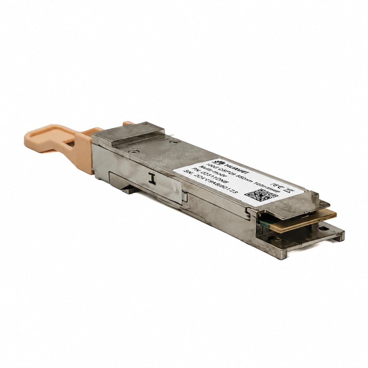
View full product specifications
Huawei 100G QSFP28 850nm MM Official Product View 2

Information below comes from the current product catalogue. Confirm the controller, software version and configuration of the installed equipment separately.

Physical Form Factor
QSFP28
Data Rate
100 Gbps
Central Wavelength
850 nm
Maximum Distance
0.1 (OM4 fiber 100m / OM3 70m) km
Fiber Type
Multi-Mode Fiber (MMF) (MMF)
Optical Connector
MPO/MTP-12 fiber-optic interface

Alarms & troubleshooting

RX_LOS (Optical RX Loss of Signal)
Switch port LINK/ACT LED off, system ALM LED solid amber
MPO-12/UPC multimode fiber disconnected or contaminated, remote TX laser disabled, or RX optical power per lane below -10.3 dBm sensitivity threshold
1. Execute 'display transceiver verbose' to inspect per-lane RX optical power levels. 2. Inspect MPO-12 connector end-faces with a fiber scope and clean with a dedicated MPO cleaner. 3. Measure remote TX launch power at 850nm to ensure it is within -8.4 to 2.4 dBm. 4. Verify MPO polarity configuration (Type-B required); replace patch cord or remote transceiver if defective.
TEMP_HIGH (Transceiver High Temperature Alarm)
Switch port LINK/ACT LED blinking amber (0.5Hz), device ALM LED solid amber
QSFP28 internal DDM temperature exceeds high threshold (75°C), caused by chassis airflow restriction, fan tray failure, or high port density heat buildup
1. Run 'display transceiver verbose' to verify real-time DDM temperature and threshold limits. 2. Check chassis fan tray status and inlet temperatures via 'display environment'; clean dust filters. 3. Ensure transceiver is fully latched and making solid thermal contact with port EMI spring fingers. 4. If rack cooling is normal and adjacent transceivers run below 55°C, replace the degraded QSFP28 unit.
BIAS_HIGH (Laser Bias Current High)
Port LINK/ACT LED blinking green or solid amber, system ALM LED illuminated
Aging 850nm VCSEL array, driver IC failure, or degraded optical output efficiency causing internal APC circuit to drive bias current above high alarm threshold (typically >10 mA)
1. Run 'display transceiver verbose' to analyze Bias Current and TX Power across all 4 channels. 2. Determine if the high bias is isolated to a single lane or affects all four channels. 3. Check if remote RX power has degraded proportionally. 4. High bias indicates irreversible VCSEL physical degradation; schedule maintenance to replace the QSFP28 transceiver.
CRC_ERR (Port FCS/CRC Error Rate Exceeded)
Port LINK/ACT LED flashing green rapidly with frame drops, system ALM LED solid amber
OM3/OM4 bend radius violation (<30mm), scratched/dirty MPO end-face inducing modal dispersion and jitter, or internal CDR (Clock and Data Recovery) lock failure
1. Run 'display interface' to monitor real-time increment of Input errors and CRC counters. 2. Inspect the OM3/OM4 patch cable physical routing and eliminate sharp bends under 30mm radius. 3. Thoroughly clean both MPO connector interfaces using an authorized optical inspection scope. 4. Verify transceiver CDR lock status via diagnostic commands; toggle port or replace multimode patch cable.
MOD_FAIL (Transceiver I2C Read Failure / Unrecognized)
Port LED off or solid amber, system ALM LED solid red
QSFP28 gold-finger pin oxidation/contamination, poor seat engagement, internal microcontroller freeze, or I2C bus contention preventing EEPROM and DDM access
1. Run 'display transceiver' to check if the module status indicates 'Uncertified' or 'Cannot read info'. 2. Eject the transceiver, inspect/clean gold-finger contacts with isopropyl alcohol wipes, and re-seat firmly. 3. Cross-test the module in another known-good 100G QSFP28 switch port to isolate cage hardware vs. module. 4. If the transceiver remains unreadable across multiple ports, replace the failed QSFP28 module.

Access Complete Maintenance & Full Alarm Troubleshooting Manual

This page lists high-frequency critical alarm codes commonly encountered in field maintenance. Comprehensive manufacturer troubleshooting matrices, board-level repair guides, detailed electrical schematics, and firmware commissioning manuals are delivered alongside equipment upon formal project procurement, accompanied by dedicated FAE technical support.

Share on-site information

  1. 01

    Identify the exact model

    Record the nameplate, system model and controller or module model.

  2. 02

    Keep the alarm details

    Record the full alarm text, indicator colour, timing and whether it persists.

  3. 03

    Describe recent changes

    Note recent replacements, software updates or configuration changes.

Record information visible in the existing interface. Electrical measurements, disassembly and replacement should follow the applicable manufacturer's manual and be performed by qualified personnel.

Your model and these details will be added to the enquiry form for you to review before sending.

Related technical articles

Browse the technical guides or send a question about this model.

View all articles

Need a replacement module or supporting equipment?

Confirm the full model, system configuration and compatibility requirements before enquiring about suitable products.

Ask about suitable products

Have a model and an on-site issue?

Share the exact model, alarm text and observed symptoms to help identify relevant information and compatibility requirements.

Request technical support