Huawei / Indoor power systems

ETP48400-C3B1 Equipment information & support

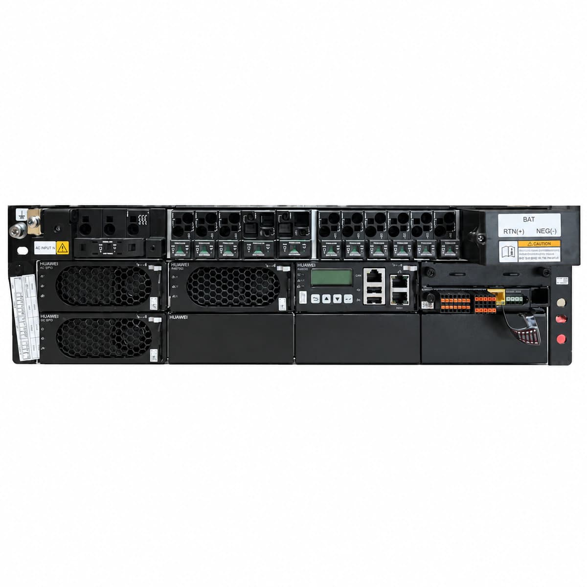
Huawei ETP48400-C3B1 is a 3U subrack high-density embedded DC power system with up to 400A output capacity, accommodating up to 8 rectifier modules managed by SMU02C controller.

Equipment information

Brand
Huawei
Equipment model
ETP48400-C3B1
Equipment type
Indoor power systems
Controller / software version
Confirm against the installed equipment
View full product specifications
ETP48400-C3B1 Official Product View 1

Information below comes from the current product catalogue. Confirm the controller, software version and configuration of the installed equipment separately.

Monitoring Controller Unit
SMU02C intelligent network management and monitoring module
DC Distribution Branches
Two-stage distribution: LLVD load disconnect + BLVD battery protection
AC Input Voltage Range
85V~300V AC (3-Phase / 1-Phase Compatible)
Physical Dimensions Spec
482.6mm (W) x 330mm (D) x 133.5mm (3U H)
System Output Capacity
400A (-48V DC)
Rectifier Module Slots
8 slots (supports mixed installation of R4850G2 / R4875G1)

Alarms & troubleshooting

AC_FAIL (AC Mains Failure / Phase Loss)
SMU controller ALM LED steady red; Rectifier green RUN LED off, red ALM LED steady on.
Upstream grid blackout, tripped AC input circuit breaker, or phase loss causing voltage below rectifier threshold (<85 VAC).
1. Measure phase-to-phase and phase-to-neutral voltages at the AC input terminal block using a digital multimeter. 2. Verify the AC input circuit breaker and SPD backup fuse are closed and free of thermal damage. 3. If AC input is nominal, inspect the rectifier backplane blind-mate connector and reseat the rectifier modules.
REC_OVP_LOCK (Rectifier DC Overvoltage Lockout)
Faulty rectifier red ALM LED steady on, yellow indicator off; SMU displays Critical Alarm.
Internal voltage control loop failure or power component short circuit triggering hardware OVP latch (>59.5 VDC).
1. Extract the locked rectifier module and measure DC busbar voltage to confirm it is within 48V-56.4V. 2. Keep the module disconnected for 3 minutes to discharge internal capacitors, then reseat it into the slot. 3. If the red ALM LED re-latches immediately, the internal circuitry is defective; replace the rectifier module.
LLVD_DISC (DC Undervoltage Load Disconnect)
SMU controller ALM LED steady red, buzzer beeping; LLVD contactor feedback status displays open.
Prolonged mains outage caused battery bank to discharge down to the LLVD disconnect threshold (typically 45.0 VDC).
1. Verify if the emergency diesel generator has started; dispatch emergency mobile power if generator failed. 2. Check DC bus voltage and total discharge current on the SMU to monitor remaining BLVD critical loads. 3. If emergency restoration of LLVD loads is authorized, adjust disconnect threshold via SMU or force manual contactor closure.
REC_FAN_FAIL (Rectifier Fan Failure / Stalled)
Faulty rectifier yellow indicator blinking, red ALM LED illuminated; SMU displays Rectifier Fan Fault.
Rectifier air intake blocked by severe dust buildup, fan bearing locked, or internal tachometer circuit failure.
1. Inspect rectifier front bezel, clear foreign debris, and clean dust filters using dry compressed air. 2. Withdraw the module and physically inspect blades for mechanical binding; spin blades manually to check bearing resistance. 3. Reseat module; if the fan fails to spin and alarm persists within 2 minutes, replace the fan assembly or entire module.
REC_COMM_FAIL (Rectifier Communication Failure)
Rectifier green RUN LED flashes slowly (0.5 Hz); SMU controller triggers 'Rectifier Comm Failure' alarm.
Poor CAN-bus contact on backplane connector, slot address allocation conflict, or damaged CAN transceiver in SMU.
1. Unlock, reseat, and latch the affected rectifier module to ensure the backplane connector mates securely. 2. Swap slot position between the faulty module and an adjacent operational module to isolate module vs. slot/backplane fault. 3. If alarm follows the module, replace the rectifier; if alarm stays at the original slot, inspect backplane pins and SMU flat cables.

Access Complete Maintenance & Full Alarm Troubleshooting Manual

This page lists high-frequency critical alarm codes commonly encountered in field maintenance. Comprehensive manufacturer troubleshooting matrices, board-level repair guides, detailed electrical schematics, and firmware commissioning manuals are delivered alongside equipment upon formal project procurement, accompanied by dedicated FAE technical support.

Share on-site information

  1. 01

    Identify the exact model

    Record the nameplate, system model and controller or module model.

  2. 02

    Keep the alarm details

    Record the full alarm text, indicator colour, timing and whether it persists.

  3. 03

    Describe recent changes

    Note recent replacements, software updates or configuration changes.

Record information visible in the existing interface. Electrical measurements, disassembly and replacement should follow the applicable manufacturer's manual and be performed by qualified personnel.

Your model and these details will be added to the enquiry form for you to review before sending.

Related technical articles

Browse the technical guides or send a question about this model.

View all articles

Need a replacement module or supporting equipment?

Confirm the full model, system configuration and compatibility requirements before enquiring about suitable products.

Ask about suitable products

Have a model and an on-site issue?

Share the exact model, alarm text and observed symptoms to help identify relevant information and compatibility requirements.

Request technical support