HEFENGQI / DC power systems

Telecom Rackmount Pure Sine Wave Inverter 48V to 220V 3kW Equipment information & support

This industrial-grade standard 19-inch 2U rackmount pure sine wave power inverter is engineered for telecom shelters and industrial automation. Operating on a nominal -48V DC bus, it delivers a continuous 3000W 220V AC output through high-frequency galvanic isolation, featuring an integrated static transfer switch for sub-4ms bypass transfer.

Equipment information

Brand
HEFENGQI
Equipment model
Telecom Rackmount Pure Sine Wave Inverter 48V to 220V 3kW
Equipment type
DC power systems
Controller / software version
Confirm against the installed equipment
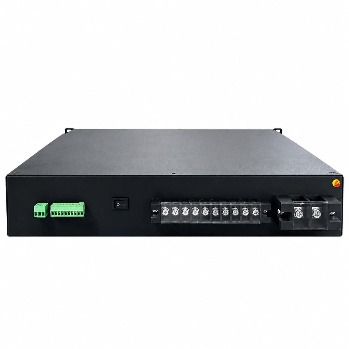
View full product specifications
HEFENGQI 48V to 220V 3kW Telecom 19-Inch 2U Rackmount Pure Sine Wave Inverter

Information below comes from the current product catalogue. Confirm the controller, software version and configuration of the installed equipment separately.

Rated System Capacity
3000VA / 3000W Full Active Power Pure Sine Wave Continuous Output
DC Input Voltage
-48V DC Nominal DC Input (-40V ~ -60V DC Wide Range)
Rated AC Output Voltage
220V AC ± 2% Pure Sine Wave with Ultra-Low Distortion (THD < 3%)
Transfer Time
≤ 4ms Seamless Static Bypass Transfer Time (Zero Drop Transfer)
Display & Control Interface
High-Definition LCD Display for Voltage, Current, Load Ratio & Alarms
Conversion Efficiency
Peak Efficiency ≥ 92% (Galvanic Isolation High-Frequency Topology)

Alarms & troubleshooting

DC_UNDER_VOLT (DC Input Low Voltage Lockout)
FAULT/ALARM LED solid red, INV LED off, continuous audible alarm
DC bus voltage drops below shutdown threshold (<42V DC); battery bank deep discharge; upstream DC breaker tripped; excessive DC cable voltage drop during high load.
1. Measure real-time voltage at the inverter rear DC input terminals with a multimeter to verify if it is below 42V DC. 2. Inspect upstream -48V DC distribution panel (PDU) circuit breaker and tighten DC terminal lugs. 3. Verify rectifier plant status; once mains returns and DC bus recovers above 46V DC, confirm inverter auto-restart or clear fault via manual reset.
INV_OVERLOAD (Inverter Output Overload / Overcurrent)
FAULT/ALARM LED solid red, BYPASS LED solid yellow (if bypass available), rapid beeping
AC output connected load exceeds 3000W rated capacity for extended time; high inrush currents from telecom server power supplies; AC distribution branch short-circuit.
1. Check the load percentage on the LCD display; immediately shed non-essential AC auxiliary loads. 2. Measure true-RMS output current with a clamp meter to ensure it stays below 13.6A (at 220V AC). 3. Inspect the sub-distribution circuit for shorts or damaged cables; once cleared, power-cycle the inverter via the front-panel switch to reset.
INV_OVER_TEMP (Inverter Module Overtemperature)
FAULT/ALARM LED solid red, INV LED flashing green or off, 1Hz audible beep
Chassis ventilation channels blocked; ambient ambient temperature exceeds operating limit (>50°C); internal IGBT heatsink thermal sensor detects temperature >85°C; dust filters clogged.
1. Check front and rear air vents; clean dust filters and ensure at least 10 cm clearance for unrestricted airflow. 2. Verify telecom equipment room HVAC/CRAC operation; bring ambient temperature down to 20°C–25°C. 3. Allow the internal heatsink to cool down below 70°C; the inverter will automatically resume operation or can be restarted.
BYPASS_UNSYNC (Bypass Utility Out of Sync / Out of Range)
BYPASS LED flashing yellow, INV LED solid green, FAULT LED off, no audible alarm
AC bypass utility input voltage exceeds acceptable tolerance (187V–253V AC) or frequency deviates from locking range (47Hz–53Hz); phase-locked loop (PLL) unlocks, preventing seamless transfer.
1. Measure bypass input voltage and frequency using a calibrated digital power analyzer to verify grid stability. 2. Review bypass upper/lower voltage limits and synchronization frequency window via front LCD / RS485 settings. 3. Once the grid stabilizes within nominal parameters, phase locking restores automatically; keep inverter on DC priority if utility power is unstable.
FAN_FAULT (Cooling Fan Locked Rotor / Failure)
FAULT/ALARM LED flashing red (0.5Hz), INV LED solid green (derated), intermittent beep
DC brushless cooling fan impeller blocked by foreign debris or bearing seized; mainboard fails to detect tachometer PWM/speed feedback pulses; loose fan harness connector.
1. Visually inspect the exhaust fans at the chassis rear; check for cables or dust clogs impeding blade rotation. 2. De-energize inverter (disconnect DC input and AC bypass), discharge internal capacitors, and verify fan terminal harness seated firmly on the PCB. 3. Spin the blades manually to check bearing resistance; replace with an identical telecommunication-grade ball-bearing DC fan module if defective.

Access Complete Maintenance & Full Alarm Troubleshooting Manual

This page lists high-frequency critical alarm codes commonly encountered in field maintenance. Comprehensive manufacturer troubleshooting matrices, board-level repair guides, detailed electrical schematics, and firmware commissioning manuals are delivered alongside equipment upon formal project procurement, accompanied by dedicated FAE technical support.

Share on-site information

  1. 01

    Identify the exact model

    Record the nameplate, system model and controller or module model.

  2. 02

    Keep the alarm details

    Record the full alarm text, indicator colour, timing and whether it persists.

  3. 03

    Describe recent changes

    Note recent replacements, software updates or configuration changes.

Record information visible in the existing interface. Electrical measurements, disassembly and replacement should follow the applicable manufacturer's manual and be performed by qualified personnel.

Your model and these details will be added to the enquiry form for you to review before sending.

Related technical articles

Browse the technical guides or send a question about this model.

View all articles

Need a replacement module or supporting equipment?

Confirm the full model, system configuration and compatibility requirements before enquiring about suitable products.

Ask about suitable products

Have a model and an on-site issue?

Share the exact model, alarm text and observed symptoms to help identify relevant information and compatibility requirements.

Request technical support