Eltek / Power management

Smartpack2 Basic Controller (242100.502) Equipment information & support

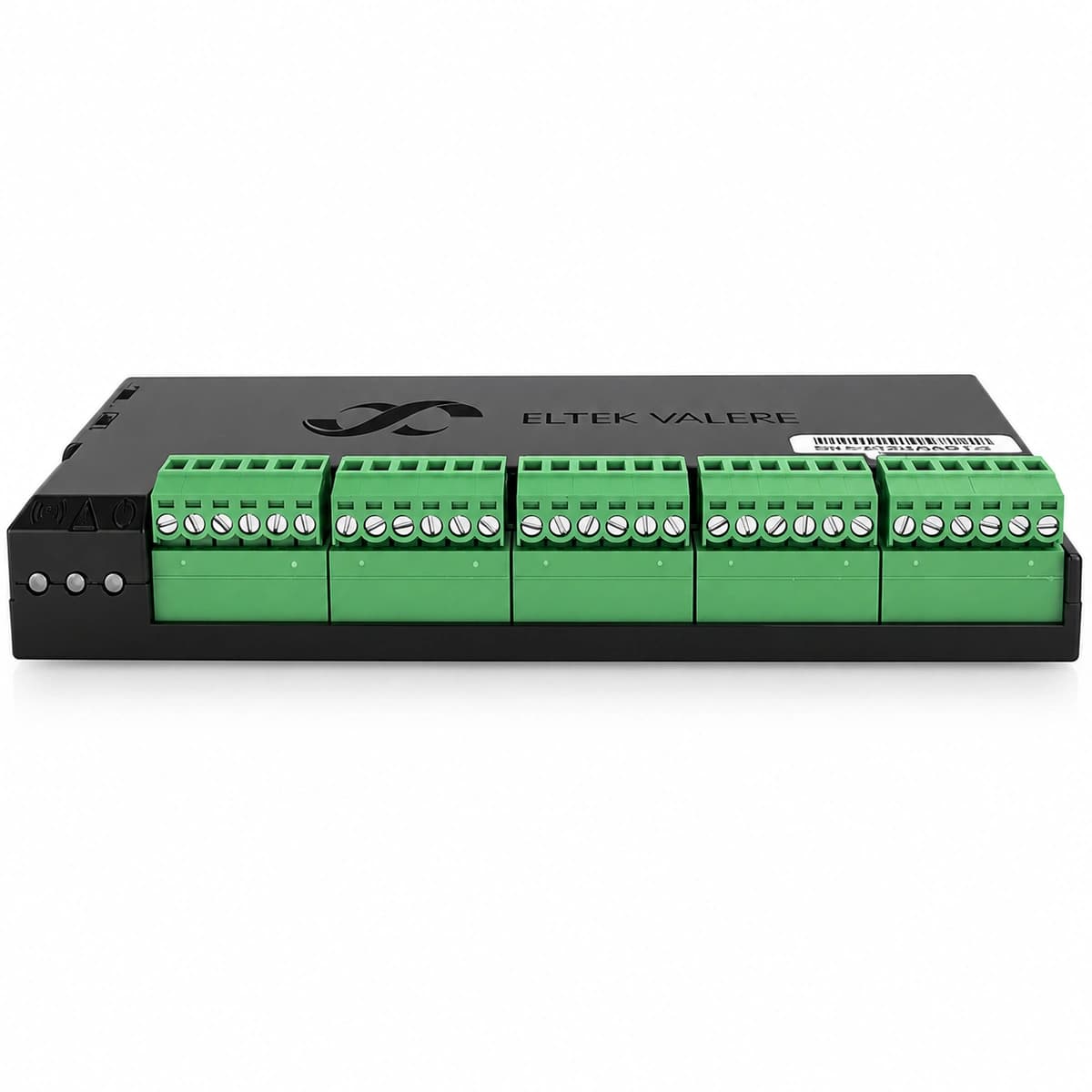
The Smartpack2 Basic (242100.502) is a specialized lower-level power system controller engineered for Eltek DC power systems, providing internal hardware metering, battery symmetry monitoring, LVD contactor actuation, and CAN communication arbitration.

Equipment information

Brand
Eltek
Equipment model
Smartpack2 Basic Controller (242100.502)
Equipment type
Power management
Controller / software version
Confirm against the installed equipment
View full product specifications
Eltek Smartpack2 Basic Controller (242100.502) Official Product View 1

Information below comes from the current product catalogue. Confirm the controller, software version and configuration of the installed equipment separately.

Alarms & troubleshooting

CAN_BUS_FAIL (CAN Bus Communication Failure)
Red Alarm LED solid, Green Normal LED blinking
Missing or mismatched 120-ohm CAN bus termination resistor, damaged or loose RJ45 communication cables, or faulty CAN transceiver on rectifiers or I/O modules pulling down the bus.
1. Verify presence and seat of the 120-ohm CAN end-of-line terminators on the controller and final nodes. 2. Sequentially disconnect RJ45 patch cables to isolate rogue rectifiers or I/O units shorting the bus. 3. Measure CAN_H to CAN_L differential resistance with power off (nominal reading should be ~60 ohms). 4. Replace any defective rectifier or I/O board failing bus arbitration and reset controller nodes.
LVBD_ACTIVE (Low Voltage Battery Disconnect)
Red Alarm LED solid, Green Normal LED solid
Extended AC mains outage depleted battery capacity below LVBD disconnect threshold (e.g., 43.2V for 48V systems), or auxiliary coil/contactor driving circuit open.
1. Confirm AC mains restoration status or dispatch mobile emergency generator to site. 2. Measure battery terminal voltage with a calibrated DMM to confirm actual state of discharge. 3. Once AC is restored, verify rectifiers ramp up and observe if the LVBD contactor recloses automatically. 4. If voltage is healthy but contactor remains open, inspect controller I/O disconnect relay outputs and coil fuses.
RECT_FAIL (Rectifier Failure & Redundancy Loss)
Amber Alarm LED solid (Faulty Rectifier Module Red LED solid)
Rectifier AC input breaker tripped, internal primary stage MOSFET/capacitor breakdown, cooling fan stall causing thermal shutdown, or damaged backplane blind-mate connector pins.
1. Access Smartpack2 UI/Web interface to identify the specific faulty rectifier ID and failure logs. 2. Check the dedicated AC branch circuit breaker and verify nominal voltage at the backplane input. 3. Unlatch and slide out the faulty rectifier; inspect air intake and cooling fan for mechanical obstruction. 4. Insert a spare Flatpack2 rectifier module of matching model; verify auto-recognition and current sharing on the display.
BATT_TEMP_HIGH (Battery High Temperature Alarm)
Amber Alarm LED solid, audible buzzer intermittent
Site battery room HVAC cooling failure, battery cell internal short-circuit initiating thermal runaway, or damaged/misplaced NTC temperature sensor sending erratic readings.
1. Scan the battery string with an infrared thermal imaging camera to detect localized cell hotspots or bulging. 2. Inspect battery room HVAC status and activate auxiliary ventilation if ambient temperature exceeds 35°C. 3. Measure NTC sensor resistance and verify connection integrity at the Smartpack2 I/O board input terminals. 4. If thermal runaway is detected, immediately lower float voltage via controller or isolate the affected string breaker.
DC_HIGH_VOLT (DC High Voltage Lockout - HVSD)
Red Alarm LED solid, Amber Alarm LED blinking
Rogue rectifier internal voltage feedback loop failure driving bus voltage above HVSD threshold (>59.0V in 48V systems), corrupt boost/float voltage setpoints, or active current share failure.
1. Measure DC busbar voltage immediately with a calibrated True-RMS multimeter to confirm overvoltage severity. 2. Observe individual rectifier current indicators to pinpoint the rogue unit outputting disproportionately high current. 3. Unseat the rogue rectifier from its slot; verify that bus voltage normalizes to nominal float level. 4. Check Smartpack2 configuration parameters (Float, Boost, HVSD trip point), correct any drift, and clear controller lockout.

Access Complete Maintenance & Full Alarm Troubleshooting Manual

This page lists high-frequency critical alarm codes commonly encountered in field maintenance. Comprehensive manufacturer troubleshooting matrices, board-level repair guides, detailed electrical schematics, and firmware commissioning manuals are delivered alongside equipment upon formal project procurement, accompanied by dedicated FAE technical support.

Share on-site information

  1. 01

    Identify the exact model

    Record the nameplate, system model and controller or module model.

  2. 02

    Keep the alarm details

    Record the full alarm text, indicator colour, timing and whether it persists.

  3. 03

    Describe recent changes

    Note recent replacements, software updates or configuration changes.

Record information visible in the existing interface. Electrical measurements, disassembly and replacement should follow the applicable manufacturer's manual and be performed by qualified personnel.

Your model and these details will be added to the enquiry form for you to review before sending.

Related technical articles

Browse the technical guides or send a question about this model.

View all articles

Need a replacement module or supporting equipment?

Confirm the full model, system configuration and compatibility requirements before enquiring about suitable products.

Ask about suitable products

Have a model and an on-site issue?

Share the exact model, alarm text and observed symptoms to help identify relevant information and compatibility requirements.

Request technical support