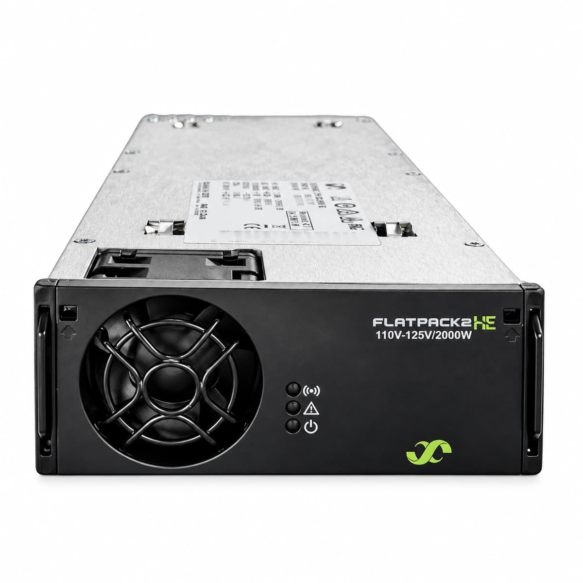
Flatpack2 48/2000 WOR HE (241115.805) Equipment information & support
The Eltek Flatpack2 48/2000 WOR HE (241115.805) is a carrier-grade, hot-pluggable switch-mode rectifier module delivering 2000W of regulated 48VDC power across a wide operating range.
Information below comes from the current product catalogue. Confirm the controller, software version and configuration of the installed equipment separately.
AC input voltage below 85 VAC or above 300 VAC; complete AC outage; tripped input MCB; loose input phase/neutral terminal connection.
1. Measure true RMS AC voltage at the backplane connector pins with a multimeter to ensure it is within 85-300 VAC.
2. Inspect the upstream AC distribution breaker (MCB) and input SPD surge suppressor status.
3. Unseat the rectifier, inspect rear blind-mate connectors for bent pins, arcing, or carbon residue, then reseat firmly.
4. If other rectifiers in the same subrack operate normally on the same feed, the internal PFC/rectification stage is defective; replace the module.
DC bus voltage exceeded hardware overvoltage shutdown threshold (typically 59.0-59.5 VDC); internal feedback control failure; selective HVSD triggered by an uncoordinated rogue rectifier.
1. Check the controller (Smartpack/Smartpack2) system voltage setpoint and current bus voltage readings.
2. Disconnect and pull the faulty rectifier out for 5 seconds to discharge internal capacitors and reset the latch, then reinsert.
3. If the rectifier immediately trips back to solid Red and drives DC voltage high, its internal control circuit is defective; replace the module.
4. If multiple units trip simultaneously, verify if the battery bank breaker opened unexpectedly, causing voltage spikes due to loss of buffer capacitance.
Yellow LED solid ON (derating); Red LED solid ON, Green OFF (complete thermal shutdown)
Ambient room/cabinet temperature exceeds specifications (>55°C); clogged intake air filters; degraded fan performance; obstructed exhaust path causing heatsink temperature to exceed safety limits.
1. Verify site air conditioning or cabinet cooling fan unit (FCU) operation to ensure inlet air is under 45°C.
2. Clean the subrack air filters and blow out dust from the rectifier front grille and internal heatsinks with dry compressed air.
3. Ensure no cables or equipment block the front-to-back airflow path.
4. If ambient temperature and airflow are normal but the unit trips immediately from cold start, the internal NTC sensor is defective; replace the module.
FAN_FAIL (Cooling Fan Failure / Speed Tachometer Fault)
Yellow LED solid ON (or blinking 1Hz depending on firmware)
Mechanical blockage or bearing seizure of the internal 48V DC fan; foreign debris around the blades; failed fan tachometer/hall sensor; blown fan drive circuit on the power board.
1. Visually check the front fan grille for foreign debris or mechanical obstruction; manually spin blades with power off to test bearing free rotation.
2. Trigger the Fan Test routine via the Smartpack controller interface to check if the fan ramps to full speed.
3. If the fan spins smoothly at full speed but the alarm remains, the tachometer sensor signal is lost; replace the fan assembly.
4. If a known-good fan does not spin at all, the mainboard fan driver circuit has failed; replace the rectifier module.
CAN_COMM_FAIL (CAN-bus Communication Failure / Module Lost)
Green LED solid ON, Yellow LED flashing (0.5Hz - 1Hz)
Dirty or bent CAN pins on backplane connector; subrack CAN-bus open circuit, shorted data pair, or missing/faulty 120-ohm bus termination resistor; controller failure; damaged internal CAN transceiver causing module to fall back to standalone operation.
1. Reseat the module firmly into its slot and verify the locking latch is fully engaged to ensure signal pin contact.
2. Check if all rectifiers in the subrack lost communication simultaneously: if yes, inspect the flat ribbon cable to the Smartpack controller and check the 120-ohm bus terminators.
3. Power off the system bus and measure resistance between CAN_H and CAN_L; it should read approximately 60 ohms (two 120-ohm resistors in parallel).
4. Move the module to a known-good slot; if the alarm follows the module, its internal CAN transceiver is defective; replace or service the unit.
Access Complete Maintenance & Full Alarm Troubleshooting Manual
This page lists high-frequency critical alarm codes commonly encountered in field maintenance. Comprehensive manufacturer troubleshooting matrices, board-level repair guides, detailed electrical schematics, and firmware commissioning manuals are delivered alongside equipment upon formal project procurement, accompanied by dedicated FAE technical support.
Record the nameplate, system model and controller or module model.
02
Keep the alarm details
Record the full alarm text, indicator colour, timing and whether it persists.
03
Describe recent changes
Note recent replacements, software updates or configuration changes.
Record information visible in the existing interface. Electrical measurements, disassembly and replacement should follow the applicable manufacturer's manual and be performed by qualified personnel.
Related technical articles
Browse the technical guides or send a question about this model.