Eltek / DC power systems

Eltek Smartpack2 Master Controller (242100.501) Equipment information & support

The Eltek Smartpack2 Master Controller (242100.501) is an advanced telecom supervisory unit engineered for centralized administration of Flatpack2 DC power systems. Featuring a vibrant 3.2-inch TFT color touch display, it functions alongside the Smartpack2 Basic controller across redundant high-speed CAN buses to deliver real-time rectifier load balancing, sophisticated battery lifecycle testing, and carrier-grade remote SNMP/Web integration.

Equipment information

Brand
Eltek
Equipment model
Eltek Smartpack2 Master Controller (242100.501)
Equipment type
DC power systems
Controller / software version
Confirm against the installed equipment
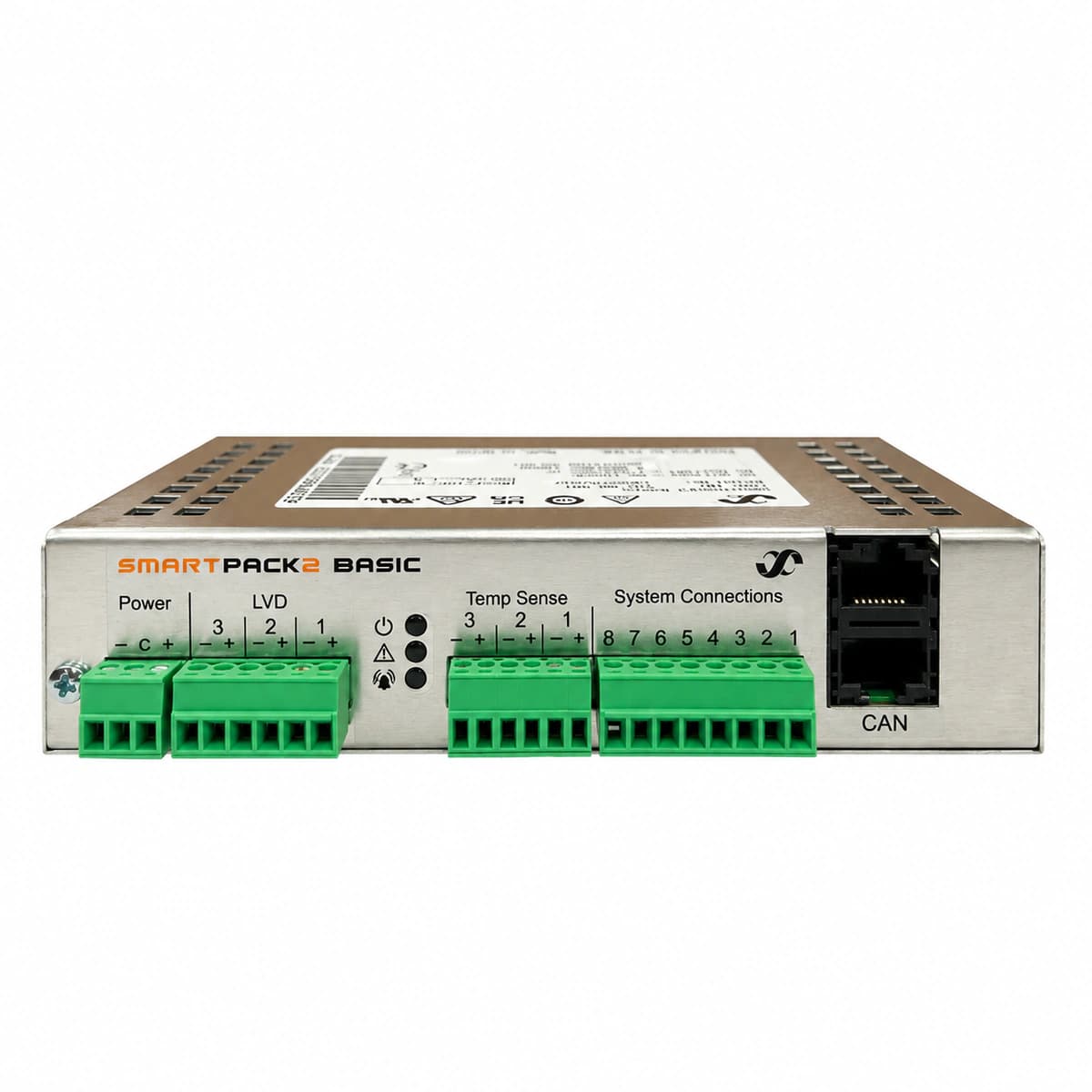
View full product specifications
Eltek Smartpack2 Master Controller (242100.501) Color TFT 18-60VDC Dual CAN Bus

Information below comes from the current product catalogue. Confirm the controller, software version and configuration of the installed equipment separately.

Controller Positioning
Smartpack2 flagship central controller unit with full-color touchscreen
Display & Control Interface
3.2-inch 320×240 high-definition full-color TFT LCD display
Internal Bus Interface
Dual high-speed CAN module communication buses (supporting cascading of hundreds of modules)
Network Management Interface
10/100M Ethernet port (SNMP v1/v2c/v3, Web, Modbus)
Battery Management Features
Advanced battery health monitoring, automated charge/discharge testing, and high-precision temperature compensation
Dry Contact Alarm Outputs
6 programmable dry contact relay alarm outputs (NO/NC selectable)

Alarms & troubleshooting

CAN_BUS_FAIL (CAN Bus Communication Failure)
Red Alarm LED solid on, Yellow Warning LED flashing, Green Power LED solid on
Interruption of CAN communication between Smartpack2 Master, Smartpack2 Basic, rectifiers, or I/O units caused by missing 120-ohm termination resistors, loose RJ45 interconnect cables, or addressing conflict.
1. Inspect the RJ45 CAN-bus patch cables connecting the Smartpack2 Master to the Smartpack2 Basic controller and rectifiers. 2. Power down the bus lines and measure line resistance across CAN_H and CAN_L; verify loop resistance is ~60 ohms (two 120-ohm terminators). 3. Access the controller menu via display or PowerSuite software, open 'Device Discovery', and isolate any unacknowledged nodes. 4. Replace faulty RJ45 cables or replace the affected node module to restore communication.
LOW_VOLT_DISC (Low DC Voltage & Battery Disconnect)
Red Alarm LED solid on, internal buzzer sounding, Green Power LED solid on
Extended AC mains outage causing battery string depletion below the Low Voltage Load Disconnect (LVLD) or Low Voltage Battery Disconnect (LVBD) thresholds, triggering contactor trip to prevent deep discharge.
1. Restore AC commercial power or deploy emergency mobile generator to power the rectifiers. 2. Confirm rectifiers start up and enter current-limited recharge mode on the Smartpack2 display. 3. If contactors fail to reconnect automatically after voltage recovery, test the Smartpack2 Basic LVD driver output and coil control fuses. 4. Use the controller menu to perform an 'LVD Manual Override' if emergency load power is urgently required under technical supervision.
BATT_FUSE_FAIL (Battery Fuse / Breaker Tripped)
Red Alarm LED solid on, Yellow Warning LED solid on
Tripped battery circuit breaker, blown fuse link in battery disconnect distribution box, or open-circuit on the battery fuse monitoring signal wire connecting to the controller digital input.
1. Visually check battery breakers/fuses; measure DC voltage drop across the fuse terminals (>0.5V indicates a blown fuse). 2. Verify there are no dead shorts across battery cables, reversed polarities, or defective degraded battery blocks. 3. Disconnect fault load/cell, then replace the blown fuse with an identical rated high-rupturing-capacity fuse (HRC) or reset the MCCB. 4. Check the monitoring sense lead termination at the Basic controller terminal block and acknowledge the alarm.
RECT_FAIL (Rectifier Failure / Redundancy Lost)
Red Alarm LED solid on, Rectifier module front LED solid red, Green Power LED solid on
Flatpack2 rectifier module internal fault, High Voltage Shutdown (HVSD) lockout, fan rotor failure, thermal protection cutoff, or internal DC-DC converter breakdown.
1. Review the Smartpack2 display 'Rectifier Status' screen to retrieve the serial number and failure code (HVSD, OverTemp, or Fan Fault). 2. If locked out by HVSD, unlatch and extract the module from the shelf, wait 30 seconds for bus discharge, and reseat firmly. 3. Inspect intake grille and fan inlet for debris, excessive dust, or blocked airflow causing thermal shutdown. 4. If the module immediately faults to a solid red LED upon reseating, replace the damaged Flatpack2 module under hot-swap operation.
BATT_TEMP_HIGH (Battery High Temperature)
Yellow Warning LED solid on, Green Power LED solid on
Site HVAC/cooling failure causing excessive battery ambient temperature, internal thermal runaway within a battery cell, or NTC sensor detachment/faulty temperature probe calibration.
1. Measure battery block temperatures with an infrared thermometer to verify real thermal elevation versus false sensor report. 2. Verify the NTC temperature sensor connection on Smartpack2 Basic terminal blocks (Sens1/Sens2); check probe resistance. 3. Inspect room HVAC systems and activate emergency exhaust ventilation immediately. 4. If thermal runaway or cell bulging is detected, lower float voltage setpoint in the controller or open the battery breaker to isolate the affected string.

Access Complete Maintenance & Full Alarm Troubleshooting Manual

This page lists high-frequency critical alarm codes commonly encountered in field maintenance. Comprehensive manufacturer troubleshooting matrices, board-level repair guides, detailed electrical schematics, and firmware commissioning manuals are delivered alongside equipment upon formal project procurement, accompanied by dedicated FAE technical support.

Share on-site information

  1. 01

    Identify the exact model

    Record the nameplate, system model and controller or module model.

  2. 02

    Keep the alarm details

    Record the full alarm text, indicator colour, timing and whether it persists.

  3. 03

    Describe recent changes

    Note recent replacements, software updates or configuration changes.

Record information visible in the existing interface. Electrical measurements, disassembly and replacement should follow the applicable manufacturer's manual and be performed by qualified personnel.

Your model and these details will be added to the enquiry form for you to review before sending.

Related technical articles

Browse the technical guides or send a question about this model.

View all articles

Need a replacement module or supporting equipment?

Confirm the full model, system configuration and compatibility requirements before enquiring about suitable products.

Ask about suitable products

Have a model and an on-site issue?

Share the exact model, alarm text and observed symptoms to help identify relevant information and compatibility requirements.

Request technical support