Delta / DC power systems

ESR-48/56A Equipment information & support

The ESR-48/56A is a high-efficiency power system designed for telecommunication facilities and industrial infrastructure.

Equipment information

Brand
Delta
Equipment model
ESR-48/56A
Equipment type
DC power systems
Controller / software version
Confirm against the installed equipment
View full product specifications
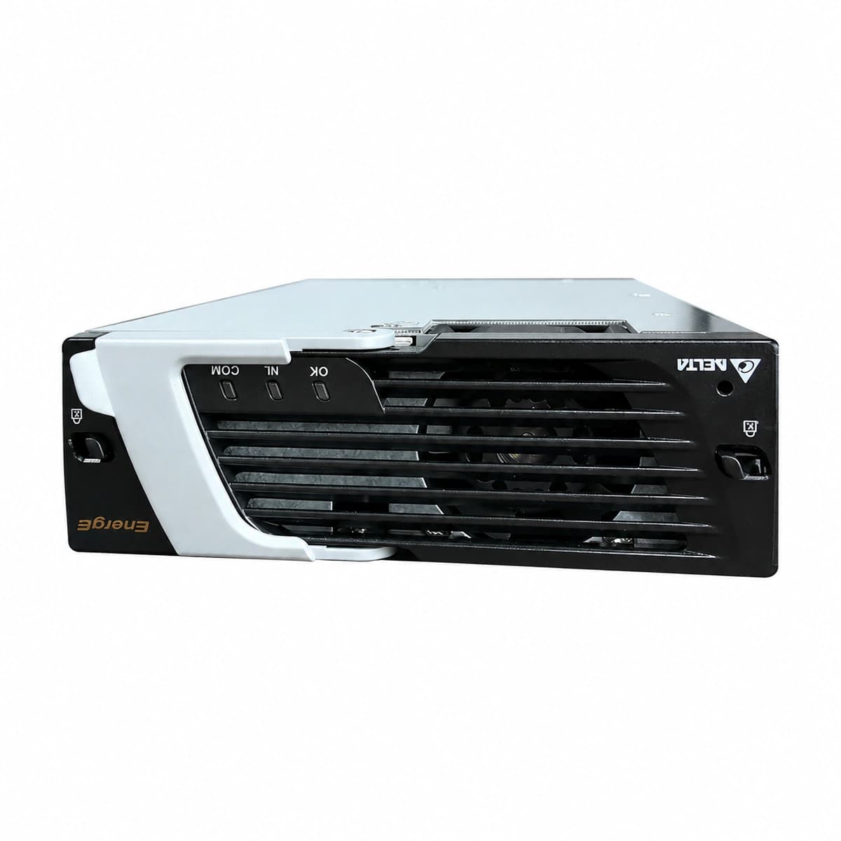
ESR-48/56A Official Product View 1

Information below comes from the current product catalogue. Confirm the controller, software version and configuration of the installed equipment separately.

AC Input Voltage Range
88VAC ~ 300VAC (Nominal 220VAC)
Nominal DC Output Voltage
-42VDC ~ -58VDC (Nominal -48VDC)
Rated Output Current
56A
Rated Output Capacity
3000W
Power Conversion Efficiency
≥95%
Cooling Method
Built-in axial fan with intelligent temperature-controlled forced-air cooling

Alarms & troubleshooting

AC_IN_FAIL (AC Input Out of Range/Failure)
Green Run LED OFF, Amber/Yellow Protection LED solid ON
Mains blackout; AC voltage below 80VAC or above 300VAC; input breaker tripped or loose connection on AC terminal block.
1. Measure AC input voltage across L-N on the module backplane using a True-RMS multimeter. 2. Verify that the dedicated AC input MCB in the distribution cabinet is closed. 3. If AC voltage is within 85-300VAC and MCB is closed, re-seat the rectifier module; replace the module if the alarm persists.
DC_OVP / HVSD (DC Overvoltage High Voltage Shutdown)
Red Alarm LED solid ON, Green Run LED OFF
Internal voltage control loop failure; invalid voltage setpoint from controller; failure of internal regulation components causing output voltage to exceed the 59.5V hardware limit.
1. Check the float/boost voltage configuration on the system controller (CSU) to verify it does not exceed 58.0VDC. 2. Unseat the fault rectifier module and wait 3 minutes to discharge internal bus capacitors, then re-insert to reset the HVSD latch. 3. If the red Alarm LED turns on immediately upon restart, replace the defective module.
OTP (Over-Temperature Protection / Derating)
Amber Protection LED solid or blinking slowly; Green Run LED OFF if shutdown occurs
Ambient temperature exceeds 55°C; cabinet air filter clogged; restricted airflow/blocked chassis vents; internal heatsink temperature sensor fault.
1. Inspect telecom shelter/room air conditioning; ensure inlet temperature is between 20°C and 25°C. 2. Clean or replace cabinet dust filters and remove obstructions from module inlet/exhaust grills. 3. Allow the rectifier to cool down; it will automatically resume operation when the heatsink temperature drops below the safe threshold (<75°C). Replace the unit if false alarms persist.
FAN_FAIL (Fan Stalled / Tachometer Failure)
Red Alarm LED ON or Amber Protection LED flashing rapidly
Rectifier cooling fan mechanically obstructed; bearing worn or seized; fan tachometer feedback circuit defective or power cable disconnected.
1. Visually check the front fan assembly with a flashlight to verify there is no physical blockage. 2. Withdraw the module and verify internal fan harness connectors are seated securely. 3. Re-insert the module and observe if the fan spins during power-on self-test; replace fan assembly or the entire rectifier if it fails to spin.
CAN_COMM_FAIL (CAN Bus Communication Loss / Current Share Fault)
Green Run LED solid ON, Amber Protection LED blinking (1Hz)
Gold-finger connector pin oxidation or poor contact on the backplane; CAN bus termination resistor open; central controller (CSU) port fault or module address conflict.
1. Remove the module and inspect backplane gold-finger pins for damage, dust, or bent contacts; clean and reseat firmly with latch locked. 2. Check the system controller (CSU) rectifier status list to identify address conflicts; initiate a bus re-scan if supported. 3. Verify the 120Ω CAN termination resistor on the power shelf; replace the rectifier module if its internal transceiver has failed while other modules communicate properly.

Access Complete Maintenance & Full Alarm Troubleshooting Manual

This page lists high-frequency critical alarm codes commonly encountered in field maintenance. Comprehensive manufacturer troubleshooting matrices, board-level repair guides, detailed electrical schematics, and firmware commissioning manuals are delivered alongside equipment upon formal project procurement, accompanied by dedicated FAE technical support.

Share on-site information

  1. 01

    Identify the exact model

    Record the nameplate, system model and controller or module model.

  2. 02

    Keep the alarm details

    Record the full alarm text, indicator colour, timing and whether it persists.

  3. 03

    Describe recent changes

    Note recent replacements, software updates or configuration changes.

Record information visible in the existing interface. Electrical measurements, disassembly and replacement should follow the applicable manufacturer's manual and be performed by qualified personnel.

Your model and these details will be added to the enquiry form for you to review before sending.

Related technical articles

Browse the technical guides or send a question about this model.

View all articles

Need a replacement module or supporting equipment?

Confirm the full model, system configuration and compatibility requirements before enquiring about suitable products.

Ask about suitable products

Have a model and an on-site issue?

Share the exact model, alarm text and observed symptoms to help identify relevant information and compatibility requirements.

Request technical support