Ce+T / DC power systems

CE+T Bravo 60Vdc/230Vac Inverter Module Equipment information & support

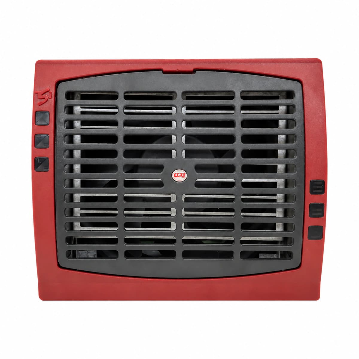
The CE+T Bravo 60Vdc/230Vac is a high-reliability modular pure sine wave telecom inverter module designed for mission-critical AC loads. Utilizing advanced Enhanced Power Conversion (EPC) topology, it achieves true 0ms seamless transfer between a 60V DC bus and 230V AC mains.

Equipment information

Brand
Ce+T
Equipment model
CE+T Bravo 60Vdc/230Vac Inverter Module
Equipment type
DC power systems
Controller / software version
Confirm against the installed equipment
View full product specifications
CE+T Bravo 60Vdc/230Vac 2500VA/2000W Modular Pure Sine Wave Telecom Inverter

Information below comes from the current product catalogue. Confirm the controller, software version and configuration of the installed equipment separately.

Rated Output Power
2500VA / 2000W pure sine wave high-frequency inverter output
DC Input Voltage
60V DC nominal DC input (range 48V to 75V DC)
Rated AC Output Voltage
230V AC single-phase pure sine wave output (THD < 1.5%)
Conversion Efficiency
≥ 96% high overall conversion efficiency in EPC mode
Transfer Time
0 ms (absolute zero-millisecond transfer between AC mains and DC battery)
Cooling Design
Built-in intelligent speed-regulated quiet airflow cooling duct with independent dust filter

Alarms & troubleshooting

DC_VOLT_FAULT (DC Input Voltage Fault)
Red Alarm LED solid, Green Run LED off
60Vdc bus voltage outside limits (<40Vdc or >75Vdc), input breaker tripped, or blown fuse.
1. Measure DC input terminals with a DMM to verify voltage is within normal range (54V–68Vdc). 2. Inspect DC distribution breaker and fuses; check for short circuits before resetting. 3. If input voltage is verified normal and connections are secure, replace the Bravo module.
INV_OVERLOAD (Inverter Output Overload/Short Circuit)
Red Alarm LED blinking, Green Output LED off
AC output current exceeds 150% rated capacity or a dead short circuit exists on the AC output line.
1. Check real-time load percentage and total output power on the Inview/T2S controller. 2. Disconnect tripped AC load breakers and check line-to-line and line-to-ground impedance. 3. Clear the load fault or redistribute excessive loads, then clear alarm via controller or reseat the module.
OVER_TEMP (Module Over-Temperature Shutdown)
Yellow Alarm LED blinking or Red solid, fans running at 100% speed
Cabinet intake air temperature exceeds 55°C, front air filters are clogged, or heatsink thermal switch tripped.
1. Check room air conditioning and ensure subrack ambient intake temperature is <40°C. 2. Inspect and vacuum clean the module front bezel dust filter and chassis ventilation grilles. 3. Allow the heatsink to cool below reset threshold for automatic restart; replace module if thermal sensor drifted.
FAN_FAIL (Cooling Fan Failure)
Yellow Alarm LED solid, intermittent supervisory buzzer
Internal DC fan tachometer signal below threshold (<1000 RPM), mechanical rotor stall by debris, or fan failure.
1. Visually check front air intake to ensure no debris or cable obstruction impedes the blades. 2. Hot-swap the module out and spin the fan manually to verify smooth rotation without bearing friction. 3. If fan spins freely but tach alarm persists upon power-up, replace the fan assembly or swap the module.
COMM_LOST (CAN Bus Communication Loss)
Green Run LED and Red Alarm LED blinking alternately
CAN bus link failure between module and Inview/T2S controller, damaged backplane pins, or missing bus termination.
1. Verify Inview/T2S controller status and check that subrack communication ribbon cables are securely seated. 2. Slide out module and inspect rear blind-mate connectors for bent pins, debris, or fretting oxidation; clean with IPA. 3. Check 120-ohm CAN termination switch on the shelf, then re-insert module firmly and lock the latch.

Access Complete Maintenance & Full Alarm Troubleshooting Manual

This page lists high-frequency critical alarm codes commonly encountered in field maintenance. Comprehensive manufacturer troubleshooting matrices, board-level repair guides, detailed electrical schematics, and firmware commissioning manuals are delivered alongside equipment upon formal project procurement, accompanied by dedicated FAE technical support.

Share on-site information

  1. 01

    Identify the exact model

    Record the nameplate, system model and controller or module model.

  2. 02

    Keep the alarm details

    Record the full alarm text, indicator colour, timing and whether it persists.

  3. 03

    Describe recent changes

    Note recent replacements, software updates or configuration changes.

Record information visible in the existing interface. Electrical measurements, disassembly and replacement should follow the applicable manufacturer's manual and be performed by qualified personnel.

Your model and these details will be added to the enquiry form for you to review before sending.

Related technical articles

Browse the technical guides or send a question about this model.

View all articles

Need a replacement module or supporting equipment?

Confirm the full model, system configuration and compatibility requirements before enquiring about suitable products.

Ask about suitable products

Have a model and an on-site issue?

Share the exact model, alarm text and observed symptoms to help identify relevant information and compatibility requirements.

Request technical support