ZTE / DC power systems

ZXDU68 T601 Equipment information & support

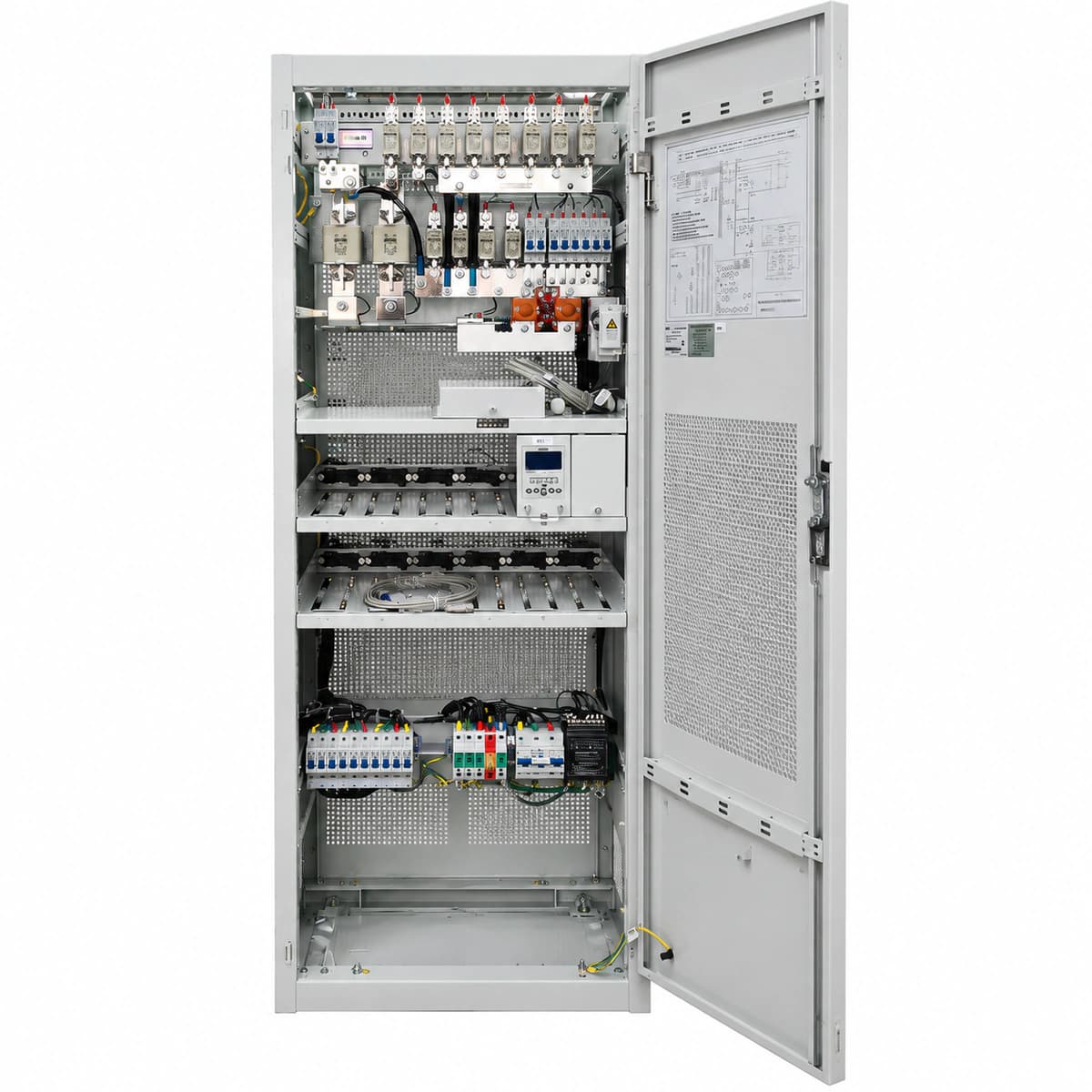
ZTE ZXDU68 T601 is a full-height indoor DC power plant delivering up to 600A with three-phase 380VAC input, scalable 50A rectifiers, and multi-tier SPD protection.

Equipment information

Brand
ZTE
Equipment model
ZXDU68 T601
Equipment type
DC power systems
Controller / software version
Confirm against the installed equipment
View full product specifications
ZXDU68 T601 Official Product View 3

Information below comes from the current product catalogue. Confirm the controller, software version and configuration of the installed equipment separately.

AC Input Voltage Range
380VAC (three-phase five-wire system 3/N/PE 50/60Hz) VAC
Nominal DC Output Voltage
-48 V DC
Rectifier Module Slots
12 × ZXD2400 (50A) Slots
Physical Dimensions Spec
2000 × 600 × 600 mm
System Monitoring Controller
CSU500 LCD monitoring unit

Alarms & troubleshooting

AC_FAIL (AC Mains Failure)
CSU Alarm LED solid red, Rectifier Power/Run LED OFF, Rectifier Alarm LED amber or off
Commercial grid blackout, AC input circuit breaker tripped, phase loss, or AC voltage out of range (<80VAC or >300VAC)
1. Measure phase-to-neutral and phase-to-phase AC input voltages with a digital multimeter. 2. Verify whether upstream AC circuit breakers and surge protection MCBs have tripped; reset after checking for short circuits. 3. If grid power is lost, monitor battery discharge state and start emergency mobile/fixed diesel generator as per NOC SOP.
REC_HVSD (Rectifier Output Overvoltage Shutdown)
Faulty rectifier Alarm LED solid red, Run LED OFF, CSU indicates Critical Overvoltage Alarm
Internal regulation control loop failure in rectifier, DC output voltage exceeded hardware threshold (>59.5V DC), triggering latching lockout
1. Identify the locked rectifier slot address via the CSU display or OSS/NMS portal. 2. Disengage and withdraw the faulty module or turn off its AC breaker; wait 3 minutes for capacitor discharge, then reseat to reset latch. 3. If the module re-trips into lockout upon powering on, internal power stage is defective; replace with a spare rectifier module.
DC_LOW_LLVD (DC Low Voltage & LLVD Disconnect)
CSU Alarm LED solid red, acoustic buzzer active, LLVD DC contactor status indicator shows tripped/open
Prolonged mains blackout causing battery depletion below LLVD threshold (default 44.0V DC); contactor dropped to protect transmission core loads
1. Immediately connect an emergency mobile generator or external AC power source to restore rectifier supply. 2. Confirm that non-critical branch breakers/contactors isolated properly and critical transmission (BLVD) loads remain operational. 3. Once AC is restored, rectifiers enter boost charge mode; verify contactor auto-recloses when bus voltage rises above reconnect threshold.
COMM_FAIL_REC (Rectifier CAN Communication Failure)
CSU Alarm LED solid amber, Rectifier Run LED flashes green (0.5Hz), Rectifier Alarm LED OFF or flashing sporadically
Poor contact on rectifier backplane connector pins, failed internal CAN transceiver chip, loose CSU ribbon cable, or bus termination resistor fault
1. Unlock and reseat the reported rectifier module; inspect backplane guide pins for oxidation, dirt, or bent pins. 2. Swap the faulty module into an adjacent empty slot; if communication establishes, the original slot backplane connector is defective. 3. If communication remains dropped across all slots (module operating in autonomous 53.5V mode), replace the rectifier module.
AC_SPD_FAIL (AC Surge Protective Device Fault)
CSU Alarm LED solid amber, mechanical indicator window on the AC SPD cartridge changes from green to red
Lightning surge energy exceeded MOV capacity, triggering thermal disconnection mechanism, or SPD remote microswitch dry-contact wire disconnected
1. Inspect the AC distribution unit (ACDU) SPD panel visually to locate cartridges displaying a red indicator. 2. Switch off the dedicated surge protection MCB, unclip and extract the degraded SPD cartridge, and insert an identical replacement (e.g., Class C/40kA). 3. Re-engage the SPD MCB, verify that the CSU alarm clears automatically, and measure ground busbar resistance (<5 Ohms).

Access Complete Maintenance & Full Alarm Troubleshooting Manual

This page lists high-frequency critical alarm codes commonly encountered in field maintenance. Comprehensive manufacturer troubleshooting matrices, board-level repair guides, detailed electrical schematics, and firmware commissioning manuals are delivered alongside equipment upon formal project procurement, accompanied by dedicated FAE technical support.

Share on-site information

  1. 01

    Identify the exact model

    Record the nameplate, system model and controller or module model.

  2. 02

    Keep the alarm details

    Record the full alarm text, indicator colour, timing and whether it persists.

  3. 03

    Describe recent changes

    Note recent replacements, software updates or configuration changes.

Record information visible in the existing interface. Electrical measurements, disassembly and replacement should follow the applicable manufacturer's manual and be performed by qualified personnel.

Your model and these details will be added to the enquiry form for you to review before sending.

Related technical articles

Browse the technical guides or send a question about this model.

View all articles

Need a replacement module or supporting equipment?

Confirm the full model, system configuration and compatibility requirements before enquiring about suitable products.

Ask about suitable products

Have a model and an on-site issue?

Share the exact model, alarm text and observed symptoms to help identify relevant information and compatibility requirements.

Request technical support