ZTE / DC power systems

ZXDU68 B301 Equipment information & support

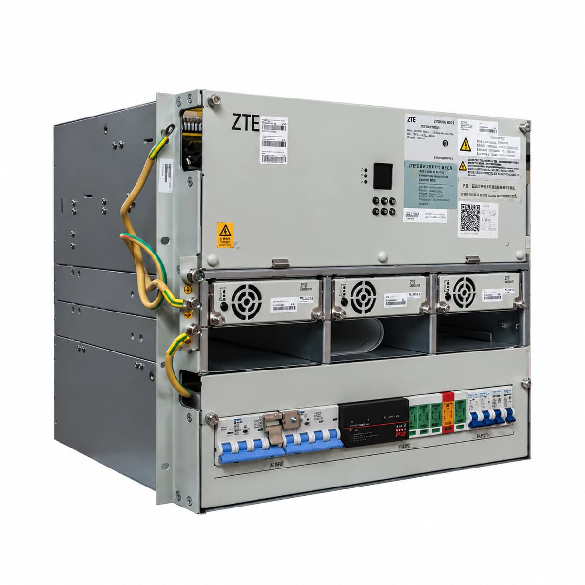
The ZTE ZXDU68 B301 is a heavy-duty embedded telecom DC power system providing up to 300A at -48V DC, holding up to six hot-swappable ZXD3000 rectifiers and a digital CSU controller.

Equipment information

Brand
ZTE
Equipment model
ZXDU68 B301
Equipment type
DC power systems
Controller / software version
Confirm against the installed equipment
View full product specifications
ZXDU68 B301 Official Product View 1

Information below comes from the current product catalogue. Confirm the controller, software version and configuration of the installed equipment separately.

Nominal Output Voltage
-48 VDC
Output Voltage Range
-42 ~ -58 VDC
System Comprehensive Efficiency
> 96.0%
Ingress Protection (IP Rating)
IP20 rack-embedded design
System Monitoring Controller
CSU502A / CSU500B ZTE centralized monitoring unit
Physical Dimensions Spec
264 × 482 × 360 mm (6U 19-inch)

Alarms & troubleshooting

AC_FAIL (AC Mains Failure / Phase Loss)
Controller ALM LED solid RED, Rectifier RUN LED OFF, Rectifier ALM LED solid YELLOW/RED
Grid blackout, upstream AC breaker tripped, or phase loss / phase voltage below 80VAC operating limit.
1. Measure phase-to-phase and phase-to-neutral voltages at the ACDU input terminal blocks using a digital multimeter. 2. Verify upstream distribution breakers and the cabinet main AC circuit breaker are engaged. 3. If line voltage is abnormal or collapsed, coordinate with the local power utility; rectifiers will automatically recover when nominal AC restores.
DC_LOW_VOLT (DC Low Voltage & LLVD Disconnect)
Controller ALM LED flashes RED (2Hz), audible alarm buzzes, LLVD contactor mechanically tripped
Extended AC outage caused deep battery discharge below LLVD threshold (default 44.0V), disconnecting non-critical loads to protect vital gear.
1. Deploy and connect an emergency diesel generator to power rectifiers and restore DC bus output. 2. If AC power is restored but contactor remains open, verify on the CSU LCD that bus voltage has reached reconnection threshold (default 48.0V). 3. Inspect battery fuse/breakers and ensure the controller enters boost charge limit mode to replenish batteries.
REC_HVSD (Rectifier DC Overvoltage Shutdown Lockout)
Faulty rectifier ALM LED solid RED, RUN LED OFF, parallel rectifiers continue normal current sharing
Internal regulation circuit failure caused module voltage to breach hardware threshold (59.5V ± 0.5V), tripping internal latch protection.
1. Partially unseat the faulty rectifier module 5cm from the backplane for 30s to discharge internal capacitance, then reseat it firmly. 2. If the module trips into red ALM lockout again upon reboot, the internal power MOSFET/PCB is defective; replace with a spare unit. 3. Check CSU parameters to verify float and boost voltage setpoints are within nominal limits (53.5V-56.4V).
CAN_COMM_FAIL (CSU to Rectifier CAN Bus Comm Failure)
Controller ALM LED solid YELLOW, LCD alerts 'Rectifier Comm Failure', rectifier RUN LED blinks (1Hz)
Loosened backplane CAN cable, defective 120-ohm termination resistor, or damaged CAN transceiver chip in a rectifier pulling the bus low.
1. Inspect and reseat the ribbon cables connecting the CSU controller to the rectifier backplanes. 2. Partially extract rectifiers one at a time; if communication recovers for the remaining modules upon pulling a specific one, that module's CAN chip has failed and needs replacement. 3. Power off the bus and measure resistance between CAN_H and CAN_L; normal range is 55-65 ohms (two 120-ohm resistors in parallel).
SPD_FAIL (AC Surge Protective Device Failure)
Controller ALM LED solid YELLOW, physical SPD module indicator window turns from GREEN to RED
Lightning surge or excessive transient overvoltage occurred on AC mains; the MOV thermal disconnector tripped, triggering the internal alarm microswitch.
1. Inspect the ACDU surge protection panel to locate which phase module (L1/L2/L3/N-PE) has turned red. 2. Switch off the dedicated SPD circuit breaker, pull out the blown plug-in cartridge, and install a genuine replacement MOV of matching rating (Class C 20-40kA). 3. Ensure the replacement cartridge sits firmly and shows a green window, then switch on the SPD breaker; the CSU alarm will clear automatically.

Access Complete Maintenance & Full Alarm Troubleshooting Manual

This page lists high-frequency critical alarm codes commonly encountered in field maintenance. Comprehensive manufacturer troubleshooting matrices, board-level repair guides, detailed electrical schematics, and firmware commissioning manuals are delivered alongside equipment upon formal project procurement, accompanied by dedicated FAE technical support.

Share on-site information

  1. 01

    Identify the exact model

    Record the nameplate, system model and controller or module model.

  2. 02

    Keep the alarm details

    Record the full alarm text, indicator colour, timing and whether it persists.

  3. 03

    Describe recent changes

    Note recent replacements, software updates or configuration changes.

Record information visible in the existing interface. Electrical measurements, disassembly and replacement should follow the applicable manufacturer's manual and be performed by qualified personnel.

Your model and these details will be added to the enquiry form for you to review before sending.

Related technical articles

Browse the technical guides or send a question about this model.

View all articles

Need a replacement module or supporting equipment?

Confirm the full model, system configuration and compatibility requirements before enquiring about suitable products.

Ask about suitable products

Have a model and an on-site issue?

Share the exact model, alarm text and observed symptoms to help identify relevant information and compatibility requirements.

Request technical support