ZTE / DC power systems

ZXDU60 S301 Equipment information & support

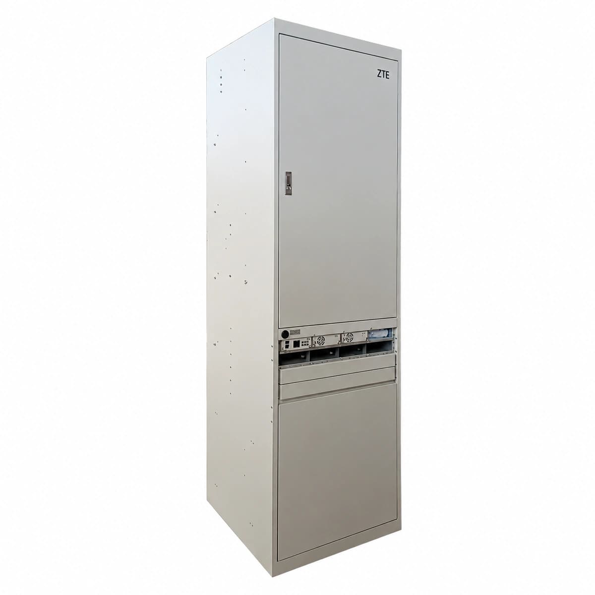
ZTE ZXDU60 S301 is an indoor floor-standing telecom DC power cabinet system delivering up to 300A (-48VDC) capacity, equipped with 6 ZXD3000 rectifier slots and CSU centralized monitoring.

Equipment information

Brand
ZTE
Equipment model
ZXDU60 S301
Equipment type
DC power systems
Controller / software version
Confirm against the installed equipment
View full product specifications
ZXDU60 S301 Official Product View 2

Information below comes from the current product catalogue. Confirm the controller, software version and configuration of the installed equipment separately.

System Monitoring Unit
CSU500B / CSU501 intelligent central monitoring unit
Physical Form Factor
indoor floor-standing integrated power supply cabinet
Battery Connection & Distribution
Dual high-capacity battery inputs with parallel protection
AC Input Voltage Range
80V~300V AC (three-phase five-wire / single-phase compatible)
System Output Capacity
300A (-48V DC)
Rectifier Module Slots
6 slots (supports ZXD3000 high-efficiency rectifier modules)

Alarms & troubleshooting

AC_FAIL (AC Mains Failure/Abnormal)
CSU ALARM LED red solid, Rectifier IN LED off, OUT LED off
Mains utility outage, phase loss, tripped AC input breaker, or upstream distribution circuit opened
1. Measure AC input phase-to-neutral and phase-to-phase voltages with a DMM to ensure they are within operating limits (85V-295V AC). 2. Inspect the main AC breaker and individual rectifier branch breakers; reset after verifying no short circuit exists. 3. If grid power is normal, verify that the AC contactor and upstream surge protector disconnectors are closed.
DC_LOW_VOLT (DC Under-Voltage / LLVD Disconnect)
CSU ALARM LED red solid, audible buzzer active, LLVD contactor open status displayed
Prolonged AC power outage leading to battery depletion, or multiple rectifier failures dropping bus voltage below LLVD threshold
1. Deploy an emergency mobile generator to restore AC feed and allow rectifiers to recharge the DC bus and batteries. 2. Verify the LLVD disconnect threshold setting in the CSU controller (typically -43.2V to -45.0V) against engineering design. 3. If AC input is present, check whether rectifiers are inhibited or if an unresolved short circuit exists on the DC distribution bars.
REC_HVSD (Rectifier Output Overvoltage Shutdown)
Faulty rectifier ALARM LED red solid, OUT LED off, other rectifiers operating normally
Internal PWM control failure, feedback optocoupler breakdown, or hardware overvoltage latch circuit triggered (> -59.5V DC)
1. Eject the affected rectifier or turn off its AC breaker; wait 5 minutes for discharge, then reinsert to reset the latch. 2. If the module trips again with a solid red ALARM LED upon power-up, the internal hardware is damaged; replace the rectifier module. 3. Check the CSU output voltage settings (float/equalize charge setpoints) to ensure correct configuration.
CAN_COMM_FAIL (Rectifier CAN Bus Communication Failure)
CSU displays module communication interruption, rectifier FAULT LED amber blinking or solid
Loose backplane CAN bus ribbon cable, oxidized module edge connector, missing 120Ω bus termination, or slot ID conflict
1. Reseat the alarmed rectifier module; inspect backplane guide pins and edge contacts for bent pins, dust, or oxidation. 2. Verify the CAN ribbon cable between backplane and CSU is secured; measure CAN_H to CAN_L resistance (nominal ~60Ω with parallel terminations). 3. Rescan rectifier slots via CSU menu; swap the module to an adjacent slot to determine if the fault follows the module or slot socket.
SPD_FAIL (AC Surge Protective Device Failure)
CSU ALARM LED amber solid, SPD physical inspection window turns from green to red
Metal Oxide Varistors (MOVs) degraded/fused due to repeated lightning surges, or auxiliary trip micro-switch disconnected
1. Visually check the AC SPD status windows to identify which phase cartridge (L1/L2/L3/NPE) has turned red. 2. Verify the SPD backup circuit breaker; if tripped and immediate reclosing fails, replace the depleted surge cartridge. 3. Hot-swap the damaged MOV module cartridge with the identical model/rating (e.g., Class C/40kA), and ensure the remote signaling micro-switch connector is plugged securely.

Access Complete Maintenance & Full Alarm Troubleshooting Manual

This page lists high-frequency critical alarm codes commonly encountered in field maintenance. Comprehensive manufacturer troubleshooting matrices, board-level repair guides, detailed electrical schematics, and firmware commissioning manuals are delivered alongside equipment upon formal project procurement, accompanied by dedicated FAE technical support.

Share on-site information

  1. 01

    Identify the exact model

    Record the nameplate, system model and controller or module model.

  2. 02

    Keep the alarm details

    Record the full alarm text, indicator colour, timing and whether it persists.

  3. 03

    Describe recent changes

    Note recent replacements, software updates or configuration changes.

Record information visible in the existing interface. Electrical measurements, disassembly and replacement should follow the applicable manufacturer's manual and be performed by qualified personnel.

Your model and these details will be added to the enquiry form for you to review before sending.

Related technical articles

Browse the technical guides or send a question about this model.

View all articles

Need a replacement module or supporting equipment?

Confirm the full model, system configuration and compatibility requirements before enquiring about suitable products.

Ask about suitable products

Have a model and an on-site issue?

Share the exact model, alarm text and observed symptoms to help identify relevant information and compatibility requirements.

Request technical support