ZTE / DC power systems

ZXDU58 B121 Equipment information & support

The ZTE ZXDU58 B121 is an integrated 19-inch rack DC power plant featuring AC input surge suppression, high-efficiency conversion, battery low-voltage disconnect (LVD), and remote network monitoring.

Equipment information

Brand
ZTE
Equipment model
ZXDU58 B121
Equipment type
DC power systems
Controller / software version
Confirm against the installed equipment
View full product specifications
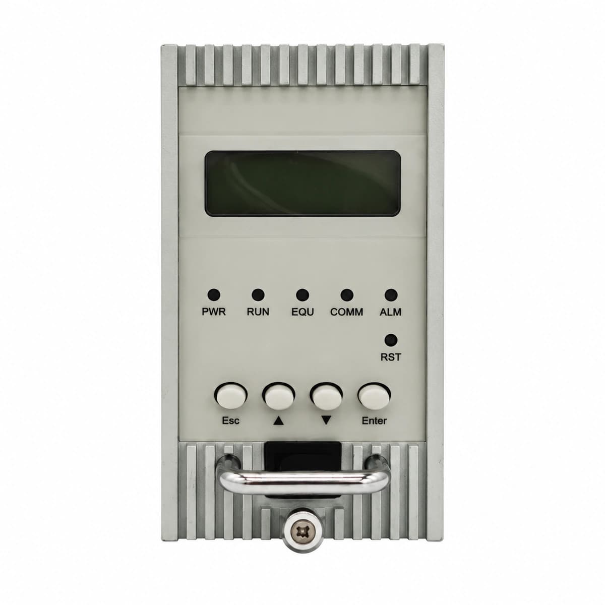
ZXDU58 B121 Official Product View 1

Information below comes from the current product catalogue. Confirm the controller, software version and configuration of the installed equipment separately.

Nominal DC Output Voltage
-48 V DC
Physical Dimensions Spec
222 (5U) × 442 × 330 mm
Operating Temperature
-25 ~ +65 °C
Rectifier Module Slots
4 × 30A Slots
AC Input Mode
Compatible with 220V single-phase / 380V three-phase

Alarms & troubleshooting

AC_FAIL (AC Mains Failure/Phase Loss)
CSU Alarm LED solid Red; Rectifier AC Input LED (IN) Off or blinking Red.
Mains grid power outage, main AC input breaker tripped, SPD surge breaker tripped, or three-phase voltage below operational threshold (<85VAC).
1. Measure L1/L2/L3 phase-to-phase and phase-to-neutral voltages at the AC distribution bar; 2. Check and reset the tripped AC breaker and SPD breaker after checking for short circuits; 3. Inspect AC contactor coil drive signals and wiring; 4. If mains voltage is normal, reseat rectifiers to inspect backplane connectors and module AC fuses.
DC_HIGH_VOLT (DC Output Overvoltage / HVSD)
CSU Alarm LED solid Red; Faulty rectifier FAULT LED solid Red, module locked in shutdown state.
CSU float/equalize voltage setpoint misconfiguration, internal rectifier PWM regulation circuit breakdown, or active current sharing bus failure driving voltage over threshold (>59.0V).
1. Verify float voltage (-53.5V nominal) and overvoltage threshold (-58.5V nominal) settings on the CSU; 2. Identify the locked module via its red FAULT LED and unplug it; 3. Measure busbar DC voltage with a multimeter to verify return to nominal level; 4. Cycle AC power to the faulty module for 3 minutes to clear hardware HVSD latch; replace rectifier if fault reoccurs immediately.
DC_LOW_VOLT (DC Undervoltage & LLVD/BLVD Disconnect)
CSU Alarm LED solid Red; LCD display shows Load Low Voltage Disconnect (LLVD) or Battery Low Voltage Disconnect (BLVD) active.
Extended AC outage exceeding battery backup reserve, depleting battery below LLVD threshold (~-45.0V) or BLVD threshold (~-43.2V); or disconnected DC sensing lead.
1. Immediately connect a mobile generator to restore AC power to the ZXDU58 system; 2. Measure actual battery terminal voltage to confirm deep discharge status; 3. Upon AC recovery, ensure LLVD/BLVD DC contactors reclose automatically; 4. Verify battery current limit on CSU (typically 0.1C10-0.15C10) to prevent thermal runaway during recharge.
REC_COMM_FAIL (Rectifier CAN Bus Communication Failure)
CSU Alarm LED Amber; Rectifier ALM LED blinking or solid Amber.
Rectifier backplane CAN gold-finger contacts oxidized or loose, backplane ribbon communication cable loose, damaged 120-ohm CAN terminal resistor, or burnt internal CAN transceiver.
1. Identify the offline module slot ID on the CSU, remove the module, and clean the rear gold-finger connectors; 2. Cross-test by inserting the module into another known-good slot to isolate module vs backplane fault; 3. Measure bus terminating resistance between CAN_H and CAN_L (should read ~60 ohms unpowered); 4. Reseat CSU communication harness; replace rectifier module if transceiver failure is confirmed.
REC_FAN_FAIL (Rectifier Fan Blocked/Failure)
CSU Alarm LED Amber; Rectifier FAULT LED solid Amber or Red, rectifier initiates current derating or thermal shutdown.
Heavy dust build-up clogging intake mesh, foreign object obstructing fan blades, open tachometer speed-feedback wire, or DC brushless fan bearing seized.
1. Extract the faulty module, inspect front air intake and rear heat sinks, and clean out dust using anti-static air; 2. Manually spin the fan blades to ensure smooth mechanical rotation without friction; 3. Re-insert the module and verify if the fan performs normal spin-up during power-on self-test; 4. If the fan does not spin or speed error persists, replace the fan tray or the complete rectifier module.

Access Complete Maintenance & Full Alarm Troubleshooting Manual

This page lists high-frequency critical alarm codes commonly encountered in field maintenance. Comprehensive manufacturer troubleshooting matrices, board-level repair guides, detailed electrical schematics, and firmware commissioning manuals are delivered alongside equipment upon formal project procurement, accompanied by dedicated FAE technical support.

Share on-site information

  1. 01

    Identify the exact model

    Record the nameplate, system model and controller or module model.

  2. 02

    Keep the alarm details

    Record the full alarm text, indicator colour, timing and whether it persists.

  3. 03

    Describe recent changes

    Note recent replacements, software updates or configuration changes.

Record information visible in the existing interface. Electrical measurements, disassembly and replacement should follow the applicable manufacturer's manual and be performed by qualified personnel.

Your model and these details will be added to the enquiry form for you to review before sending.

Related technical articles

Browse the technical guides or send a question about this model.

View all articles

Need a replacement module or supporting equipment?

Confirm the full model, system configuration and compatibility requirements before enquiring about suitable products.

Ask about suitable products

Have a model and an on-site issue?

Share the exact model, alarm text and observed symptoms to help identify relevant information and compatibility requirements.

Request technical support